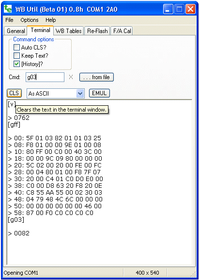
wbUTIL - Terminal

Terminal (Software User Interface) : Allows direct user interaction with the wideband controller or display's inbuilt user interface.

Apart from issuing commands that are executed immediately, a number of related functions are also launched from this tab, including:
  • Command File Interpreter - A file is read (use the [. . . from file] button) and the commands specified within are automatically executed. This is useful for longer and commonly used sequences of commands or for performing complex configuration.

  • Wideband Emulator - (use the [EMUL] button) simulates the output from a WBo2 controller and is primarily to test different display configurations and for driving logging software.
A display may be connected using the reprogramming adaptor supplied with the display.

Terminal - Buttons, Options, etc.

In the command area, immediately to the right of Cmd :, you enter commands to the device currently connected to the COM port (refer to the General tab. Results are sent back and displayed in the results-area in the lower section of the screen. You can enlarge the display area by resizing it - you will be prevent from making it smaller than 400 x 540.

The way data is displayed can be controlled with the drop-down menu to the right of the [CLS] button. - selecting As ASCII works for most commands (selecting Bytes in Hex or one of the Frame modes shows raw binary data in a more readable format).

  • The Auto CLS? check box enables the result area to be cleared before each command is issued. The screen can be manually cleared using the [CLS] button.

  • If the Keep Text? check box is enabled, the text of the next command entered will be retained. This can be useful if a number of similar commands are to be entered - the command is executed each time the keyboard Enter key is pressed.

  • When the [History]? check box is enabled, commands entered are echoed in the results display area.

    Note : A Command History is maintained and pressing the keyboard's up and down (cursor) arrows, when the cursor is in the command text area, will scroll through the commands previously issued.

  • The [. . . from file] button is used to open the Command Processor window. This is used to processes commands from a file.

  • The [EMUL] button opens the WBo2 Emulator. The emulator sends out a configurable RS232 data stream so it looks like it comes from a real WBo2 controller.

Configuration Memory and Configuration Variables

Typically a command either performs an immediate action or reads or modifies a memory variable. Memory variables are stored in either RAM memory or EE memory. RAM memory is used for variables (RAM variables) that are accessed often. EE memory is used for tables and variables that are not often accessed. Configuration RAM memory variables (conf vars) control how the device is configured. During start-up, as a means of configuring the device, conf vars are pre-set by copying them all from a special area of EE memory (called conf EE memory). To permanently re-configure a device the conf RAM variables must be written back to conf EE memory. Different commands modify these different areas of memory

Configuration Variables (called Conf Vars). Conf vars modify the operation of the device and are located in a special part of memory called Configuration Memory or Conf RAM (sometimes abbreviated to just Conf). When the device is powered up Conf RAM is created from a permanent copy of itself in EEPROM memory (abbreviated to EE memory). Other less often used tables are saved directly in EEPROM memory and are not copied to Conf RAM.

Commands are used to read and write Conf RAM (g, s), copy it to EEPROM (w), reload Conf RAM from EEPROM (l), and other commands (r and u which may change in the future). EE tables that are not copied to Conf RAM are read and written with their own specific commands that use a 16 bit address (a & e). Conf commands use an abbreviated 8 bit address as there are less than 255 Conf RAM locations (actual Conf size depends on the device).

Some commands relate to a third type of optional memory the device may contain called on-board logging memory. A rudimentary file system is used to allow access to the larger memory sizes (see the k, q, x, y and z commands

Other commands allow hardware registers to be set up for testing, calibration and other maintenance tasks like re-flashing.

Warning : Controllers will normally put out a continuous binary data stream. To Windows® the controller data stream looks a little like that from a serial mouse. So, make sure you have the wideband unit disconnected from the COM or USB port, or powered down, when booting your PC.

Note: binary data from a controller may appear as a garbage so you need to either select the correct As Xxxx filter, or temporarily turn off continuous data by issuing the command tf to the controller. Another scheme is to slow the data speed from the controller (use command s047f).

Basic Commands - ASCII text with Parameters

The format of the commands is quite rigid to avoid complex error handling that would take up code space in the device. No white space is allowed between the single command letter and its parameter(s). The parameters are either zero (none), one, two or four hexadecimal (hex) characters in width. An example of this is the e command used to read EEPROM memory.

      e012345   - 7 character command writes 45 (hex) to address 0123 (EEPROM)

In the above command 0123 is the 16 bit (4 hex digit) address and 45 (hex) is the data to write (to EEPROM).

All commands provide feedback that they have successfully completed, or they return the error string Err <cmd> where <cmd> is the command that could not be executed. In the above example, the e012345 command will return the following string:

      > 0045    - data 45 was written correctly to EEPROM

Note that there is a <cr><lf> pair before the > symbol. Commands that are not understood (usually because the parameters have the wrong size) are indicated as follows:

      Err g00d  - g00d is an error (g00 is a good command!)

The following table lists all documented commands that may or may not work as advertised on all controllers. They are not in alphabetic order, but grouped by function. The first column (Cmd) is the single command letter. The second column lists the parameter(s). The third column indicates the format of the response and fourth column indicates what action results from the command. The last column provides more explanation.

Cmd Param(s) Resp. Action Notes
v - vers Display the 4 character hex firmware version This should match the HXF file. Also used for software reflash setup.
t n
n = 0
n = F
0 < n < F
 
<data>
 
<data>
serial logging control, n = single hex character
  • Send a single Tx frame if Tx auto-gen is disabled
  • Stop Tx Frames being sent (disable Tx auto-gen)
  • Start Tx Frames being sent (enable Tx auto-gen)
  • The Tx auto-gen flag controls whether serial data frames are automatically generated or not. A single Tx frame will be generated with the t0 command. The actual format of the data is determined by a Conf variable.
    a n ad16 data16 Read EEPROM (n=0) or RAM (n=8)
  • MSB of ad16=0 read byte from EEPROM
  • MSB of ad16=1 read word from RAM
  • The AVR architecture divides non-code memory into EEPROM and RAM, The a and e commands read and write to those two memory types with the MSB of the address determining which type is accessed. eg: e002345 writes 45 to EEPROM address 0023 - the word returned is address (0023). for the a command the returned value is the 8 bit data there (as a 16 bit value).
    e ad16 dat8 ad16 Write EEPROM (MSB=0) or RAM (MSB=1)
    MSB as for the a command.
    s adr8 dat8 code set config byte at adr8 to value dat8 The first section of RAM is called Conf RAM as special configuration data is stored there at run-time. Conf RAM can be read with the g and written with the s commands.
    g adr8 ≠ FF
    adr8 = FF
    data
  • get config byte at 8 bit address adr8
  • gets and formats all config data
  • l - code (ie. lower-case L) reload conf-RAM based data from EEPROM Conf RAM is loaded from EEPROM at startup (like l command) to make access to it much faster. If conf RAM changes then the complete EEPROM copy can be updated with the w command.
    See next section for extended commands using w
    w - code write conf-RAM based config data to EEPROM
    r - code reload conf-RAM from ROM (note: command may change) these two commands (r & u are debug commands and may change or be removed in future versions.
    u - code update system params from conf-RAM
    b vers (none) Software reflash setup. vers = firmware version. Vers must match the firmware (see v command).
    See next section for extended commands using b
    m n state Sets the WBo2 main state n
  • OFF (0) Debug (and initial startup) state
  • RUN (1) Normal running state
  • CAL (2) Calibration state
  • This does not work for displays (returns an error). Use this only for special testing/debug.
    d n dat12 w sets DAC to value dat12 (address embedded)
  • 0xxx: both DACs
  • 2xxx: DAC A (DACV)
  • 3xxx: DAC B (WBVO)
  • The (two channel, 12 bit) hardware DAC is used to both control the wideband sensor and to provide a wideband output voltage.
    p n dat10 w sets PWM value to dat10 (address embedded)
  • 0xxx: PWM A (SVout)
  • 1xxx: PWM B (NBsim)
  • The (10 bit) PWM output is used to generate the lower accuracy NBsim and SVout voltages.
    i chn mux data reads ADC channel chn with MUX set to mux The CPU reads analog data from a channel via a MUX input. Different hardware may use different channels and mux input assignments.
    k - string Read the memory-type string
  • Err k = Firmware doesn't support onboard-memory
  • FFFF = No memory found (or hardware error)
  • BF80 = SST 1 Megabyte memory
  • Logging to on-board memory and retrieval of logged data is controlled by these 5 commands. The original 2A0 hardware supported just the 32 kbyte EE memory with the x and z commands. Newer hardware (2A1) supported the 1 Mbyte logging module (SST) and added the q, y & z commands.
    More information can be found here.
    See next section for extended commands using q
    q
    -
    nn

    aabb
    hhhhhh
    query SST on-board logging memory status
  • aa = sectors used, bb = sesions saved
  • 24 bit sessions length (bytes used)
  • x n ptr stop/start logging to on-board logging memory
  • n = 0, stop logging
  • n = 1, start logging
  • n = blank - return the current storage pointer
  • y adr16 -
    0040
  • set logging memory storage pointer to adr16
  • clear logging memory (reset the pointer)
  • z - <data> dump logged data stored in onboard memory

    Extended Commands (Interpreted Intelligently!)

    As noted above, commands interpreted by the device are purposely very simple and have a rigid structure. The primary reason for this is to limit the size of the device's command interpreter (saving code space for useful functionality). Another consideration is to make it easy for someone to enter data, and to this end we can use some intelligence within WButil's terminal itself.

    To simplify the entry of data larger than 8 bits in width, the terminal program pre-interprets command-letters b, w & q so they are given new meaning. When the menu item Options -> Interpret Commands Intelligently is checked. These modified commands either read, or if data is supplied, write, Conf-RAM in units of byte (8 bits), word (16 bits) or quad-byte (32 bits). The format of <data> is hex by default, but adding a period (ie. a dot) after the data changes the <format> to decimal. Data can be explicitly declared as hex with the $ symbol. Negative data (but only for decimals) can be entered too by preceding it with a minus (ie. hyphen). Note that <address> is always in hex form. The form of commands is shown below - note that the space between the <address> and <data> is mandatory:

        <command-letter> <address>                      - Read data
        <command-letter> <address> <data>[<format>]     - Write data
    

    Here are some examples.

          w 23           - No data so read word at address 0x023
          b 23 19.       - write the same word with data byte 0x13 (decimal 19.)
          b 23 -2.       - write -2. (= 0xFFFE) to the same address
          w 12 567       - write hex word 0567 to address 012
          q ab 12345678  - write hex 12345678 to address 0AB
    

    Note that the interpretation of these commands occurs in the WButil program itself. A single intelligent-command may result in multiple simple-commands being issued to the device.