|
Wideband sensors require a controller because they are more complex than a standard narrowband sensor.
They are more accurate because of this complexity, but this means they require a technically complex controller for them to work at all.
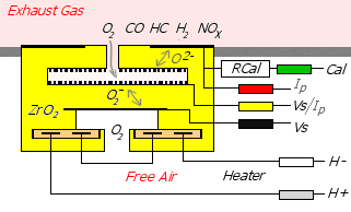
The sensor itself can be thought of as two closely connected parts that are electrically heated to a dull read heat:
- A narrow-band sensor to detect the oxygen concentration within a small chamber.
- A pump cell that transports oxygen ions to or from the surface of this small chamber.
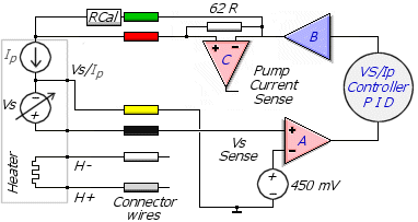
As we will see, the wideband sensor is operated by current that is pumped into or out of the pump cell by the wideband controller electronics.
This is fundamentally different to a narrowband sensor that produces its narrowband voltage, without any external electronics, when heated to operating temperature.
To understand wideband, we must first understand narrowband sensors:
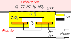
Narrow Band Sensors
Narrowband sensors have between one and four wires.
One of the wires will always be the signal voltage.
A second wire can be used to isolate the ground end of the signal to reduce signal noise.
Three and four wire sensors add a heating element so the sensor starts operating faster and more reliably.
The image at left shows a representation of a 4-wire version - in practical narrowband designs the sensor is often shaped as
a thimble to maximise surface area exposed to the exhaust gas.
The electrical heater is used to raise the temperature of the Zirconium Dioxide
(ZrO2) material that the sensor element is made from.
Zirconium Dioxide (often doped with Yttrium oxide)
is an important substance that maintains mechanical rigidity while
capable of conducting an electric current when in a molten (red hot) state.
The sensor current is carried by oxygen ions that become available only when the sensor is hot enough.
The Platinum covering is both conductive and promotes a catalytic reaction
between oxygen ions and partially burned fuel.
The Nernst equation
describes the voltage produced as a result of this catalytic reaction involving Oxygen ions, Platinum catalyst and exhaust gas.
- Vs = (RT/4F)*ln(pO2air/pO2exh)
pO2 = partial pressure across gas boundary
The pO2xxx is the partial pressure of oxygen, and is a convenient representation of the oxygen concentration
on each side of the oxygen sensor. The RT/4F term can be thought of as a constant multiplied by temperature T.
|  When using a 5-wire (wideband) sensor we make certain assumptions about the environment the sensor is used in,
for example we assume the sensor is used to measure the exhaust byproducts of fairly complete combustion.
The combustion can be internal, as in a conventional vehicle or external combustion,
as in a furnace or other device consuming fuel and oxygen.
If these conditions are altered then inappropriate readings may result.
For example, if a miss-fire occurs and unburnt droplets of fuel go through the motor,
then the sensor will read lean as it will not detect the liquid fuel.
When tuning a vehicle, you should not rely solely on the reading from a sensor.
Let your common sense, and a little knowledge of how the sensor works, guide you.

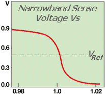 What this equation says is that with rich mixtures, where there's almost no oxygen, but lots of free fuel,
the voltage Vs produced by the sensor will be fairly high.
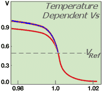 Around stoich some free oxygen becomes available and the voltage produced by the sensor rapidly drops.
The graph at left shows how Vs rapidly switches from a voltage around 0.9 Volts to around 0.1 Volt over a very small Lambda (or AFR) range.
This rapid switching is one reason narrowband sensors are not accurate in the rich region, where most power tuning takes place.
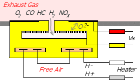
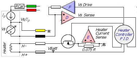 The heater of most 5-wire sensors is designed to produce maximum heating power at a lower voltage than the vehicle's battery voltage.
This is to allow for voltage losses in the controller circuitry and for more rapid heat up from cold,
but it also means that for a long sensor life, the controller should be careful not to stress
the sensor during warmup when large enough currents to destroy the heater can flow.