Environment with High Moisture (?) Content (Case 2)
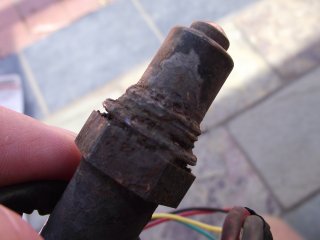
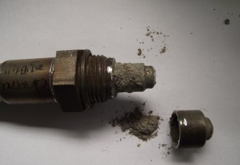
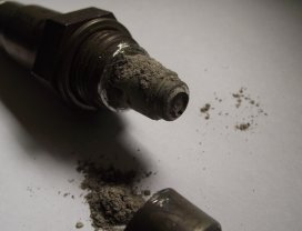
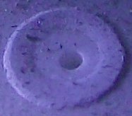
Here's a sensor we received from a flue application that appears to have lots of condensation on its external surface.
We can only speculate that it was in a high humidity/moisture environment.
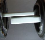
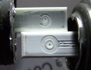
We took off the two protection tubes in one operation and noted
that whatever had blocked the space between the inner and out protection tube was not loose ash (like we found in case 1).
We speculate that a high moisture (or perhaps even tar) content somehow conspired to
cement the ash into a hard and gas-tight material.
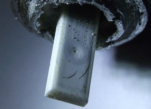
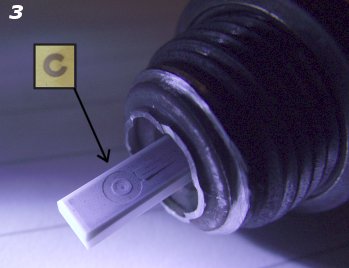
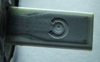
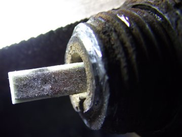
In fact, as this close up shows the ash or tar (or mixture) that found its
way past the inner protection tube has also coated the sensor's outer surface.
Remember that the sensor runs at a dull red heat - the ash/tar appears to have "bonded" to the surface.
Although we said the sensor worked fine once we took off the protection tubes exposing it to free-air.
In fact, once we connected the sensor to a controller, the sensor's calibration point changed continuously (and quite rapidly)
over a period of several hours the calibration value (as determined by WButils's calibration function)
changed to the point at which we thought the sensor was performing correctly.
This may be due to impurities or contaminants affecting the diffusion chamber's catalytic surfaces now having
a chance to escape, or it may be due to oxygen now being able to combine with impurities that found their way into
the sensor's diffusion chamber.
This sensor, presented to us as "dead", was bought back to life by simply removing the physical obstruction,
caused by soot/ash/tar, lodging between the inner and outer protection tubes.
|  This section may provide useful for people contemplating using oxygen sensors in situations other than vehicle exhaust systems.
We present photos and other information we have collected over years of receiving user feedback.
If you have a sensor that fails unexpectedly then feel free to contact us to ask if we'd like to see it for inclusion in this section.
