 The temporary adapter PCB is shown here wired up to the DB9 connector using three short
lengths of wire (the cut-off tails from resistors work well).
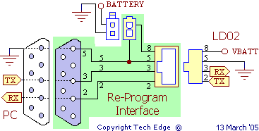
Note the folowing connections :
- DB9-2 -- RX-PCB
- DB9-3 -- TX-PCB
- DB9-5 -- GND symbol
The white 2 pin Molex® connector is wired as shown (note orientation relative to the PCB).
- longer Molex® lead (at the top) goes to a short piece of wire which is in turn
connected to the 12V point on the PCB.
- shorter Molex® lead (bottom) is soldered directly to the edge of the large circular PCB hole (this is the GND symbol point).
The image below shows the Molex® connector a little better.
- be aware that not all RJ45 PCB sockets have the same pin-outs. If you ever replace the RJ45 connector, do so with one of the same pin-out.
- the correct DB9 is a DB9-S or female DB-9 socket.


 Only the light green parts of the circuit are on this interface PCB.
Do not be confused with the RX & TX designations -
they refer to the signals as seen by the PC, not the LD02.
 When re-flashing LD02, remember that LD02 must be manually set to Config Mode
by pressing the top button while power is applied to the unit.
Half way through the re-flash, LD02 will be commanded to do a soft reboot,
and unless the top button is still pressed at this point, LD02 will come up in normal mode
and the EEPROM part of the re-flash will fail.
In this case, it's easiest to simply reflash with the EE Only check box ticked
(make sure you have version 1.6 or later of the