3H1 Technical Information
Technical Overview
| Outputs
| Inputs
| Jumper-shunts
| LED Diagnostics
| Logging
The 3H1 unit, without cables, weighs close to 300 grams,
and measures 117 x 110 mm with height of 30 mm.
The mounting tabs protrude an extra 15 mm each side
and the connectors add a further 10 mm back and front.
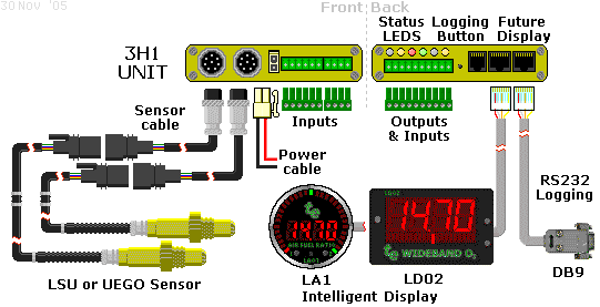
Sensor, power and display cables are compatible with the other units
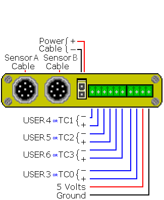
Front of 3H1.
|

Back of 3H1.
|
3H1 Outputs = WBlin+/-, SVout, NBsim & RS232
As 3H1's major function is to measure AFR (or Lambda), the unit provides three
software configurable voltage outputs
(WBlin, NBsim) & SVout.
All three outputs can be re-programmed to cover different output voltage ranges vs. lambda (or AFR) ranges.
The default voltage output ranges are shown in the graphs below (right hand column).
As well, an RS232 data stream provides digitally precise information on sensed AFR and all logged inputs.
3H1's outputs are described in detail in the following paragraphs.
Note: Pin 3/8 refers to pin 3 on the 8 pin connector.
Looking at the 8 pin connector in the above diagram, that is the USR5- (or TC2-) input.
Note:
All the outputs described below produce a voltage on an output pin and use a second pin as the signal's reference point.
The GND pin (shown at right) serves as the reference point for the
NBsim & SVout signals.
The WB LIN - signal serves as the reference point for the main WBlin output.
|

|
Wideband Outputs - WBlin0- Pin 6/10 & WBlin0+ Pin 7/10
Wideband Outputs - WBlin1- Pin 8/10 & WBlin1+ Pin 9/10

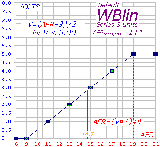
The most accurate of the 3 voltage outputs is WBlin which is generated by a 12 bit DAC
using a 65 word lookup table (with linear interpolation for improved resolution).
3H1 adds the capability to program WBlin to a maximum of 8.192 Volts.
A special feature of WBlin is what we have called a differential output.
The WBlin+ output pin (left pin in the image) is the signal, and the WBlin- output pin is the ground reference output.
This arrangement is designed to reduce the amount of noise and possible voltage offset errors seen by a device connected to WBlin.
The WBlin differential output is described fully here (but note that 3H1 provides up to 8.192 Volts on WBlin).
WBlin can be re-programmed using the Config utility
to cover any part of the AFR range from Lambda = 0.6 to free-air over the 0 to 8 Volt range.
The default linear wideband output is shown in the image at right.
Note that the maximum voltage is 5.00 Volts at an AFR of 19.0
(* see note-1 below).
With the default mapping as shown, when an AFR of 19 is reached, the output clamps at 5.00 Volts - this is for
100% compatibility with previous wideband models, and to ensure 5 Volt input on logging devices are not overloaded.
For the default mapping shown, to convert WBlin to an AFR,
simply multiply the measured voltage by 2 and add 9.
The advantage of a linear output is that it's easy to write a conversion function
from the wideband voltage to AFR.
* Note-1:
Remember that WBo2 is a Lambda meter and is "calibrated" to display AFR for fuels with a stoich AFR of 14.7 (ie. "unleaded").
For other fuels that don't have a stoich value of 14.7, the x-axis (AFR) of the graph shown here should be modified.
* Note-2:
while the WBlin output is accurate, the Lambda data in the RS232 data frame is inherently more accurate
and does not suffer from some possible sources of signal degradation that beset all analog data.
* Note-3:
3H1 has two wideband channels, and WBlin0 is mapped to wideband channel A (left circular 8 pin connector) &
WBlin1 is mapped to wideband channel B (right connector).
|
As well as WBlin the SVout & NBsim outputs are available.
They use a 10 bit PWM circuit which is less accurate (WBlin is 12 bits) and slightly noisier too.
Both outputs can be re-programmed using the Config utility.
Simulated Narrowband Output - NBsim Pin 10/10

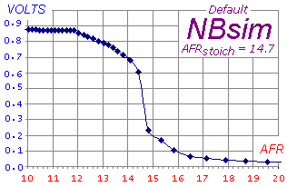
The NBsim output (called NB OUT on the label at left) is
designed to be compatible with the raw output of a Bosch LSM-11 sensor.
Refer to this eXcel spreadsheet
for the graph of this default NBsim vs AFR.
Note that the curve is for a narrowband sensor.
NBsim is produced by the onboard microcontroller
using a 10 bit PWM A/D converter (with two pole filter), and a 65 word lookup table with linear interpolation.
Unlike WBlin, a range from 0 up to 5 Volt (single ended, not differential) output is available.
The default NBsim 0 to 1 volt range reduces the number of possible steps to around 200 (~5 mV per step).
As NBsim can re-programmed it is possible to do a number of
interesting things such as fooling the engine's ECU (if equipped with a NB sensor)
into running richer or leaner than it would do otherwise.
|
Compatibility Output - SVout Pin 5-RJ11 & Pin 1-RJ45
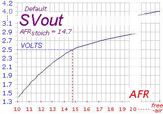
This 0 to 5 Volt signal (called SV OUT)
can be programmed independently of the WBlin and NBsim signals.
SVout originally drove the now discontinued LD01 display (taken from the RJ45 pin 1).
The default AFR vs. SVout relationship is shown in the Vout table/graph page.
SVout varies from a minimum of about
1.0 Volt for a very rich mixture (Lambda=0.6 or AFR=9), to 2.50 Volts
for a stoic mixture, and to 3.1 Volts for a lean mixture (AFR=25).
In free-air, a correctly calibrated unit should produce SVout of exactly 4.00 Volts (ie. 20.9% oxygen at 1 bar pressure).
To generate SVout, the processor uses a 65 word lookup table with linear interpolation.
It converts the normalised pump current (Ipx - representing AFR) into a 10 bit value that is passed to a hardware PWM
(Pulse Width Modulation) A/D converter with a two pole filter.
SVout is compatible with the Vout signal from the original
oz-diy-wb unit (and the 1.5 unit's Vwb).
It can be used to drive the analog LD01 display (or the older 5301 if you change its connector).
Note that the 12 bit WBlin can be re-programmed to use the SVout table,
so if you're not using WBlin and you want a more accurate SVout voltage,
you should consider reprogramming WBlin.
Remember however that SVout covers the full range of full-rich (Lambda=0.6) to free-air, the voltage range is small (less than 3 Volts)
so measuring resolution is reduced compared to using a smaller AFR range over a larger voltage range.
|
RS232 - Rx Pin 2-RJ45 & Tx Pin 3-RJ45 Transmit/Receive
|
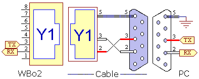
The 3H1 has two RJ45 connectors that carry RS232 and other signals (see below).
Each RJ45 carries the same signals.
The unit transmits logged data on its Tx line [pin 3 - RJ45] and
receives commands (from PC or display) and code updates from a PC on its Rx line [pin 2 - RJ45].
The diagram at left shows the wires within the cable and also the connections at each end.
Note the pin names change from left to right - the WB unit's Tx pin transmits to the PC's Rx pin.
[pin 5 - RJ45] is the shield for the Rx and Tx data lines as well as being the return data path.
|
WBo2 to PC cable
Here's an image of the actual RS232 cable for connection between a PC and the WB unit.
The cable is used for either logging to a PC, or for re-flashing its code (under control of a PC).
|

|
Other RJ45 Outputs - SVout Pin 1,
GND Pin 5 &
Vbatt Pin 8
|
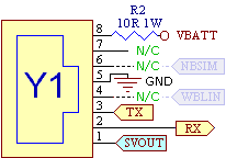
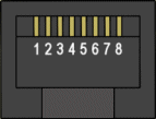 The SVout signal [pin 1-RJ45] (pins are numbered from the left)
is described in detail above.
This connection is intended for analog displays like the LD01 and
those displays will also use Vbatt & GND described below.
The RJ45 connector signal names are shown at right.
A fused, protected and partially filtered battery voltage Vbatt
is available from [pin 8-RJ45] (this is the right most RJ45 signal).
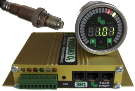
This output is provided to power other devices such as the LA1 or LD02 display.
It should only be connected to devices that will draw small currents; typically less than 100 milliamps.
Excessive current consumption may cause heating of an internal 10 ohm dropping/protection resistor.
A ground GND point [pin 5-RJ45] is provided as a return for the RS232 and Vbatt connections.
Note that there are number of unconnected outputs (N/C = No Connection) on each of the RJ-45 connectors.
Those N/C's that have uses on other wideband units are shown "greyed in" and include WBlin (pin 4) and NBsim (pin 6).
|
6 Pin RJ11 Connector - LSS Tx & SVout
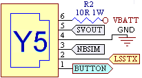 The 6 pin RJ11 connector is designed for use with an intelligent serial display.
Its primary feature is a second serial channel called the Low Speed Serial (LSS) interface
which has a 1200 baud data rate (ie. low speed) which is adequate for most displays.
Additionally there is a duplicate of the SVout signal also found on the two RJ45 connectors, as well as a Logging Button connection, that can be brought out to an external pushbutton and used on, for instance, a dashboard. The Button signal is connected to Ground to activate it.
The RJ11 connector includes the following signals :
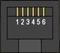
BUTTON [pin 1-RJ11] Connected to Ground via an external pushbutton to duplicate logging button.
LSS Tx [pin 2-RJ11] is not currently supported in firmware.
Vbatt [pin 6-RJ11] &
GND [pin 4-RJ11]
provide current limited power and a return GND for the external display.
NBsim [pin 3-RJ11] is a duplicate of the NBsim signal found on the Green Connector.
SVout [pin 5-RJ11] is a duplicate of the SVout signal found on the RJ45 Connectors.
|
|
3H1 INPUTS
Thermocouple and Analog
3H1 has 6 analog inputs spread across the three green removable connectors as shown at right.
- On the 10 pin connector (image top right), are two inputs USR 1
& USR 2. They are 0 to 5 Volt single ended
inputs that are referenced to GND and can be used to read voltages produced
by TPS, MAP and other voltage sensors or even external thermocouple
amplifiers producing up to a 5 Volt signal. USR1 & USR2 are NOT designed for direct thermocouple input.
- On the split 6 + 4 pin connector are four differential inputs labelled from the left
as TC1, TC2, TC3 & USR3 (image lower right).
The two single ended 5 Volt inputs (USR1 & USR2) cannot be changed, but
the 4 differential inputs (TC1 to TC3 & USR3) can be set up,
using the DIP switches described below, either as general purpose
0-5 Volt inputs or as thermocouple inputs.
By default all the inputs marked as USR are 0-5 Volt and
the inputs marked TC are for K-type thermocouple.
The default and alternate setup of the DIP switches is shown in this table:
| Name (default) |
USR 1 |
USR 2 |
TC 1 |
TC 2 |
TC 3 |
USR 3 |
GND |
| Alternate name |
USR 4 |
USR 5 |
USR 6 |
TC 4 |
| on green connector |
10 pin |
6 pin |
4 pin |
| Pin Number |
1 |
2 |
1, 2 |
3, 4 |
5, 6 |
1, 2 |
4 |
To change the analog input hardware from these default,
the case must be opened and the configuration DIP switches (shown below) set.
As noted, the logging software settings must also be changed (see later).
|
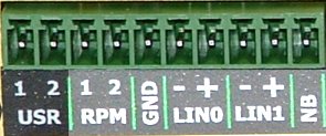
10 pin - USR1 & USR2, 0-5 Volt inputs (above).
6 pin TC1, TC2, TC3, and 4 pin USR3 (below).
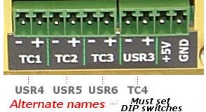
|
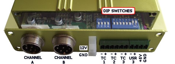
3H analog input options are to be found inside the case on two DIP switches
located behind the split (6 + 4 way) green connector.
To access the DIP switches only the four screws, securing the end-plate shown, need to be removed.
The green single 10 way connector at the back of the case must also be unplugged so the PCB
may then be slid out from the case.
Special Note: the colour, orientation and numbering of the switches may change,
but the left bank (see image) will always be 4 switches wide, and the right bank 8.
The ON and OFF position of the small switches is important and this will be detailed in the following text.
Please re-read the previous paragraph as some early units were shipped with the DIP switches orienatated
the "wrong" way compared with the illustrations and text below - remember that the ON and OFF
status of the switch is what you need to set.
|
|
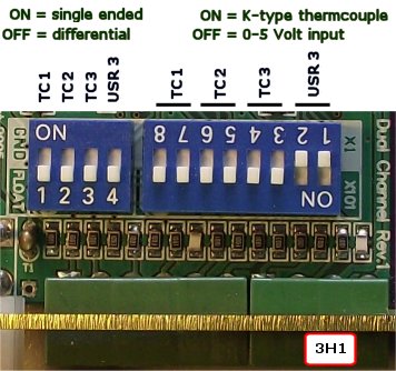 The image shows the two blocks of DIP switches. They are divided into a group to set either single-ended (ON)
or differential (OFF) mode, and the other group to set the input to either use
K-type thermocouple amplifier (ON = x101 amplify) or for
0-5 Volt use (OFF = x1 amplify).
The image (the default as shipped) shows that TC1 to TC3 are set for differential & thermocouple mode,
and USR3 is set for differential & 0-5 Volt input mode.
Differential vs. Single Ended Mode
Differential mode measures a voltage connected between the (+) and the (-) inputs.
The voltage recorded is the difference between the two inputs.
In general, the (-) input should be at or above the GND voltage, and the (+) input should be no greater than 5 Volts
measured from the GND pin.
In differentail mode the (-) inputs must always be connectd to the sensor or to the GND point on the green connector.
Single-ended mode measures a voltage connected between the input and the GND point.
The USR1 and USR2 inputs don't have (-) inputs (or rather, their (-) inputs are permanently connected to GND within the unit).
Although the DIP switches may be used to convert a differential input to a single-ended input,
the same can be acheived (without opening the case) by connecting a wire between the (-) input
and the GND point (pin 4 on the 4 way green connector).
Thermocouple vs. 0-5 Volt input
There are two differences between inputs labelled as thermocouple (TC) and user (USR) inputs.
- TC channel DIP switches are set by default to have a 101 times amplification factor.
This means a 49.5 milliVolt signal will be amplified to 5.00 Volts (49.5 mVolts this
is the uncompensated K-type thermocouple voltage corresponding to 1,220°C).
- TC channels (for firmware up to xx62) are logged as 10 bit data values
(ie. 1023 = Maximum Volts), whereas USR channels are logged as 13 bit values (8192 = Maximum Volts).
Note carefully that this 10/13 bit difference is embedded in the controllers firware
and is not changed by the DIP switches.
These differences mean that as well as setting the hardware DIP switches (amplification x1 or x101)
the logging software must also be told to use 10 bit or 13 bit values.
|
Thermocouple Inputs - TC1+/- to TC4+/-

As noted above, up to four thermocouple input channels are available from a pool of 6 analog channels.
when used with standard K-type thermocouples a differential channel,
is set up with a gain of 101 (see above DIP switch settings).
In this case a temperature range of ambient to just over 1,200 °C can be recorded.
An input voltage of 49.5 milliVolts (0.0495 Volts) will have an effective range of 0.0495 * 101 = 5.00 Volts.
Each thermocouple is attached directly to the two screw terminals [left=(-)ve, right=(+)ve]
as shown in the image at left.
An internal thermistor, placed near the screw terminals, is used to measure ambient temperature so that ice-point compensation
can be applied to the raw thermocouple data to give better accuracy.
Some thermocouples use a single wire with the return via the vehicle's earth system.
This type of sensor will be noisier than a two wire sensor.
Any single wire input should have its corresponding DIP switch set to the GND position
if a return wire from the -ve input cannot be connected physically close to the sensor itself.
We don't necessarily recommend these people, but http://www.exhaustgas.com
should be consulted to give you an idea of what's available.
Check their part number 4018-48-R-W (48 inch long wire, weld on bung, stinger model).
Or for their probes
look at the bottom of the page for the products
they make to suit Westach instruments. All of these probes are
manufactured with terminals which suit the green connector really well.
The image shows the (-)ve terminal insulated with heatshrink.
The tabs on the EGT probe's end wires have been "streamlined"
to prevent hitting each other during operation.
The K-type thermocouples are made in either a clamp-on style, a weld-on style,
a high quality bullet probe, or the stinger probes (2 year warranty).
Their bullet probes work on 1000 hp/cylinder top fuel cars and need to last 100 passes.
Here's a pop-up image of a hose-clamp style EGT clamp.
Thermocouples generate a voltage that depends on the difference between the "hot" junction
where two dissimilar metals are joined, and the "cold" junction.
Basic data for K-type thermocouples is available from NIST at
http://srdata.nist.gov/its90/main/its90_main_page.html.
|
analog Inputs USR1 to USR6+/-
Up to six analog inputs (USR1 through USR6 - see above
DIP switch
configuration) are available.
The inputs have a digital resolution of 10 bits and are sampled at a rate determined by
logging configuration parameters.
All channels have at least a 10k ohm input impedance (and typically much higher)
and cover the range of 0 to 5 Volts (when the DIP switches are set to the X1 position).
The 10 bit resolution means variation as small as 5 milliVolts can be detected, but in practice
the noise limit inherent in any digital system sets the resolution to as low as 15 to 20 milliVolts.
The two inputs USR1 [pin 10/10] & USR2 [pin 9/10]
are single ended and use the vehicle GND as their negative reference.
The USR3 input [pin 8/10=(+)ve, 7/10=(-)ve] is differential (and may be configured as TC4).
USR4 to USR6 may also be configured for thermocouple use, and when the
DIP switch is set in the X1 position, work as normal 0-5 Volts inputs.
Note that single ended input mode is selected by setting the DIP switch to the GND position.
Tacho Input - RPM1 (Pin 3/10) & RPM2 (Pin 4/10)
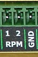
3H1 has an RPM channel that is captured for logging.
Two inputs are provided, Designated RPM1 and RPM2.
RPM1 may be directly connected to a COIL (or a Tach signal as generated by some vehicles) or to a lower voltage "logic level" signal, dependent on the setting of an internal jumper (marked COIL or PULSE).
RPM2 may only be connected to a "logic level" signal, and is intended for applications like Vehicle Speed Sensors. As this is a new feature of 3H1 and 3B1, not all software currently supports this input.
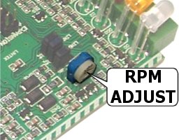
The image at right (click for enlargement)
shows the location of VR1 inside the 3H1 case.
VR1 can be adjusted to reject high frequency noise signals that sometimes interfere with RPM capture.
More information can be found further down the page in the section describing Jumper Shunts.
The RPM1 input [pin 7/10] normally connects to the wire going between the points and the COIL.
On vehicles that have electronic ignition and a distributor,
you would connect to the point between the transistor switch (or ignition amplifier) and the coil.
The COIL input should never be connected to any voltage larger than 12 Volts or damage to the WBo2 unit may result. Be aware that the RPM Jumper must be in the "COIL" position when connected to high voltage.
With the RPM Jumper in the "PULSE" position, RPM1 can be connected to any lower voltage signal
that produces a 5 volt pulse at some small multiple of the engine's revs.
Unfortunately the loading (low input impedance) of the Lo input sometimes makes it infeasible to connect
to sensitive circuits such as an inductive crank angle sensor.
|
|
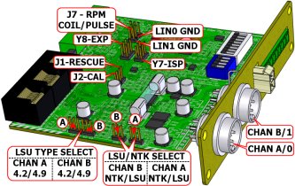
3H1 Jumper-Shunt Locations
The following sections describe how hardware options are set using on board jumper-shunts (often just called jumpers).
These shunts are :
- DIP - switches used instead of jumpers. They are describe above.
- J1 - RESCUE jumper OFF except when rescue re-flashing.
- J2 - calibrate jumper (should be ON always)
- J3 - WBlin0-GND jumper (on to select GND reference, more info. here).
- J4 - WBlin1-GND jumper (on to select GND reference, more info. here).
- J5 - NTK or LSU jumper selects the type of sensor to use. note: channel A/0
- J6 - NTK or LSU jumper selects the type of sensor to use. note: channel B/1
- J7 - RPM jumper (Select between PULSE and COIL input).
- W3 - for Bosch sensors 4.2/4.9 jumper selects LSU-4.0/4.2 or for LSU-4.9. note: channel A/0
- W4 - for Bosch sensors 4.2/4.9 jumper selects LSU-4.0/4.2 or for LSU-4.9. note: channel B/1
- Y7 - EXP Header expansion conector for future add-on functionality.
- Y8 - ISP Header factory programming (mentioned but not described below).
|
|
Click on the image or here for an enlarged popup of the jumper-shunt locations
which are list from the lowest number first (not their order of importance).
|
Reflashing - Firmware Updates [J1]

It is important to remember this jumper-shunt does not need to be accessed,
except when the 3H1's internal code memory has become corrupted,
through a very rare power glitch or unsuccessful firmware upgrading.
The reflash process is described in the reflash utility section
and this can normally be accomplished without opening the case.
The image at right shows the location of the rescue-reflash jumper-shunt in the middle of the Y8 header.
Click for an enlarged photo-image popup.
Y8 is the 8 pin expansion header that contains J2.
The board does NOT have an inactive position for the J2 jumper-shunt,
so simply position it on one of the header pins when the unit is not being re-flashed.
|
Calibrate Jumper - Leave ON [J2]
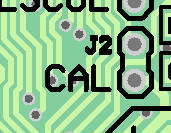
Normally this jumper-shunt should be left ON and left alone.
This jumper is intended for factory use only, and if removed the unit will not power up in the correct mode for normal operation. It may be useful when troubleshooting a non-working unit, to check that this jumper is installed correctly.
|
NTK UEGO & Bosch LSU Support [J5] & [J6]
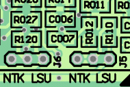 The 3H1 supports both the Bosch LSU sensor (all LSU 4.0, LSU 4.2 & 4.9 models).
as well as the NTK UEGO sensor (L1H1, L2H2 & related models)
Two jumpers are used per Wideband channel:
- W3/W4 - Sets either LSU (Bosch LSU models 4.0, 4.2 or 4.9 sensors)
or NTK (Either L1H1, L2H2, or similar sensors), Described in more detail below.
- J5/J6 - Sets between Bosch LSU 4.0/4.2 or 4.9)
which have quite different operating requirements.
Go here for more information on the sensors supported by 3H1,
but remember the sensor's actual connector may be different between otherwise compatible sensors.
To change the sensor between UEGO (NTK) and LSU (Bosch), two things must be done:
- Change the hardware which entails :
- Changing the 3H1-to-sensor cable to match the new sensor (see cable information here).
- Set J3 jumper shunt, for
either the NTK or LSU.
- For the LSU sensor select either the 4.2 (covers 4.0 as well) or the 4.9 position.
- Change the firmware by re-flashing 3H1 with the latest firmware for that sensor.

Be very careful to match the J3 jumper shunt's position correctly as using the NTK setting with an LSU, or vice versa,
may damage the sensor or the 3H1 control unit.
This warning is particularly relevant if you swap from LSU to NTK.
It's quite clear which is the NTK or the LSU position.
Symptoms of a jumper in the wrong position include sensors that never get hot enough
(see LED diagnostics below), or it gets too hot and is damaged.
|
Bosch LSU 4.0, 4.2 & 4.9 Support [W3] & [W4]
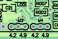 The 3H1 supports various models of Bosch LSU sensor, Changing between Bosch LSU 4.0/4.2 or 4.9 requires a different firmware file. Note that both Wideband channels must have the same model sensor. Two jumpers are used to select the LSU model type:
- W3 - Selects between Bosch LSU 4.0/4.2 or 4.9 for Wideband Channel A
- W4 - Selects between Bosch LSU 4.0/4.2 or 4.9 for Wideband Channel B
Remember to change the firmware by re-flashing 3H1 with the latest firmware for that sensor.
|
WBlin - GND Reference [J3] & [J4]
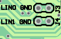 This shunt controls the WBlin+ output's reference input (WBlin-).
This topic is discussed here.
It is important to note that incorrectly setting this jumper can result in either:
- Excessive WBlin+ noise (mostly heater switching transients at 30 Hz) on WBlin+
(with shunt installed = ON when it should be OFF and WBlin- goes to the input amp's GND).
- floating WBlin+ output that can exceed 5 Volts or go below 0 Volts
(shunt is OFF when WBlin- is left floating).
Note that the effect of the J3 & J4 shunts can be reproduced by wiring WBlin- & GND together with a short piece of wire.
This obviates opening the case to access J3 & J4 (but make sure J3 & J4 are off when you need them off).
|
Pulse Input - [J7]
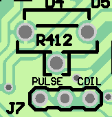 This shunt controls the conditioning circuit for the RPM1 input, and can be set to either of two positions.
- PULSE - Is intended for low voltage (0-5v) inputs, such as an ECU or Ignition Module output. Unfortunately, the loading (low input impedance) of the RPM input sometimes makes it infeasible to connect to sensitive circuits such as an inductive crank angle sensor.
- COIL - When in this position, RPM1 May be connected to the terminal of a conventional ignition coil system. (or a Tach signal as generated by some vehicles)
On vehicles that have electronic ignition and a distributor you would connect to the point between the transistor switch (or ignition amplifier) and the coil. The COIL input should never be connected to any voltage greater than 12 Volts or damage to the WBo2 unit may result.
3H1 Also has an RPM2 input, intended for uses such as Vehicle Speed Sensors (VSS). This is a permanent PULSE input, as described above, and may be used at the same time as the RPM1 input.
|
Operation of the LEDs (Error, Heater, Logging)
The unit has six LEDs that describe the current status of the wideband unit.
They are, from left to right,
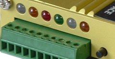
 CLEAR = Error/Status LED - Channel A
The FIRST LED is a bi-colour (red/green) LED, and appears as translucent white when OFF.
It is labelled as ERR STATUS A and shows either good operational status (solid GREEN)
or an error status (flashing RED) for error conditions (and during sensor warmup).
The flashing frequency and ON-OFF ratio, as described below, indicates the status displayed.
 AMBER = Heater Power LED - Channel A.
The SECOND LED is labelled as STATUS HTR A and during normal operation
shows the level of power supplied to the sensor's heater (there is a just-visible 30 Hz flicker).
If the sensor or sensor cable is damaged or removed, or the battery voltage drops below 10.5 Volts or above 19.5 Volts
you should see an irregular, but dim, sharp flicker.
 RED = Logging LED.
The THIRD red LED is dedicated to indicate on-board logging status as described below.
note: other WBo2 models use the red LED to also show error/status, but this is not the case with 3H1.
 GREEN = Power LED.
The FOURTH green LED indicates system power for the 3H1 unit.
 CLEAR = Error/Status LED - Channel B
The FIFTH LED is a bi-colour (red/green) LED, and appears as translucent white when OFF.
It is labelled as ERR STATUS B and shows either good operational status (solid GREEN)
or an error status (flashing RED) for error conditions (and during sensor warmup).
The flashing frequency and ON-OFF ratio, as described below, indicates the status displayed.
 AMBER = Heater Power LED - Channel B.
The SIXTH LED is labelled as STATUS HTR B and during normal operation
shows the level of power supplied to the sensor's heater (there is a just-visible 30 Hz flicker).
If the sensor or sensor cable is damaged or removed, or the battery voltage drops below 10.5 Volts or above 19.5 Volts
you should see an irregular, but dim, sharp flicker.
The image above right shows the 3H1 unit's LED panel.
Diagnostics from the STATUS & AMBER LEDs
Please note that some browsers may not render these animated GIF images as we intended, so be sure to read the explanation.
And, we have only shown the LEDs that are important to the explanation.
 Normal Operation :
After warmup, and during normal operation (with no on-board logging activity),
the two left LEDs should be glowing reasonably brightly.
The CLEAR LED should be lit GREEN and
the AMBER LED should also be brightly lit but with a just perceptible flicker (at 30 Hz).
The intensity of the AMBER LED will give some idea of how much power is being used to maintain the
sensor's heater temperature.
A very hot exhaust will produce a dimmer glow, and a sudden transient (like letting off the throttle)
may cause a noticeable change in the intensity or flickering - this is quite normal.
 Normal - Heating :
After the unit is turned on, the normal heating cycle will cause the CLEAR LED
to flash about once a second with a short sharp RED ON flash, and longer OFF time
where the LED remains unlit (and NOT green).
The AMBER LED will produce a small amount of flicker (30 Hz), but should be brightly LIT.
This should last 20 to 30 seconds for a cold sensor heating up.
If the sensor warm-up time is much over 30 seconds then either the battery voltage may be low
or the sensor is placed where it is being excessively cooled by the gas flowing past it.
A cool sensor position may result in reduced sensor life and inaccurate measurements.
 Sensor Error :
If there is a problem with the sensor, the unit-to-sensor cable, or perhaps the unit itself,
the regular RED flashing of the CLEAR LED occurs.
Carefully note that the AMBER LED will have a very noticeable, but dim, flicker.
The CLEAR LED will not be showing any GREEN.
Possible things to check for are :
- Low battery voltage - it must be above about 10.5 Volts and below about 19.5 Volts.
- Undamaged unit-to-sensor cable making good connection to the unit and to the sensor itself.
- Undamaged sensor - hold the sensor's sealing washer and shake it. It should not rattle.
- Does the firmware and hardware configuration (internal shunts) matches the sensor used?
PID Warnings :
A number of conditions, that are not necessarily errors, but indications of potential problems, are reported.
Something called a PID controls the sensor. There are two software PIDs used by WBo2,
one for the heater, and one for the Lambda/AFR control function.
A PID operates within certain control limits and will produce a warning if the control limits are reached
and/or the operational parameters are exceeded.
PID warnings are reported by a short RED ON flash of the LEFT LED,
which will otherwise be showing the operational GREEN colour.
It's possible for quite normal transient conditions to cause the RED to flash.
As long as the AMBER LED remains on, and the CLEAR LED shows GREEN when not RED,
then this is an indication of a PID warning.
PID warnings may simply be indicating rapid changes in heating or cooling of the sensor (eg. full throttle to DFCO),
and/or rapid changes in the ambient air-fuel ratio.
If this occurs without an explanation (ie. without a corresponding rapid change in throttle position)
then it may be an indication of an intermittent somewhere in the wiring, an aging sensor,
or possibly a poor sensor position that is on the limit of the sensor's heating ability,
or at the other extreme, is just too hot (remember, the controller can heat the sensor but not cool it).
As the RS232 data stream carries more detailed status information, then either
the LA1, LD02
or the TEWBlog logger may give more information about the condition.

The HEATER PID's sharp RED single flash is shown at left.
This condition may indicate the sensor is positioned where it is either too hot or too cool.
The heating time, from cold, for a sensor in a "neutral position" is about 20-25 seconds.
If it takes considerably longer to reach operating temperature then the position may be too cool.
|
![]()
|

The WIDEBAND PID's sharp RED double flash as shown here (note the 1-2, 1-2 beat).
The most common cause for this is an old or contaminated sensor.
Lead (from leaded petrol), Zinc (from galvanising), Silicon (from gaskets, etc.), Ethylene Glycol (from anti-freeze), etc.
are all contaminants that will "kill" your wideband sensor quite quickly.
Running it too cool will also have the same effect.
|
|
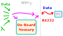
Logging Operation - Button & Status LED.
3H1 has 1 Mbyte of on-board logging memory, this is up from the 32 kbytes of 2B0.
1 Mbyte is enough memory to save about 60 minutes of data sampled at 10 times a second.
The diagram at right is an overview of how 3H1's logging works (see here for detailed technical info).
It shows 3H1 collecting data from both the Lambda sensor and the other inputs (described above).
That data can be immediately sent out the RS232 connection,
and it can also be saved in the on-board memory.
Data saving is controlled by the ON-BOARD LOGGING
button to the right of the red LED.
Getting that data back is controlled by software commands that are issued to 3H1 from a PC (TEWBLog does this automatically).
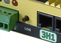
On-Board Logging :
Operation of 3H1's logging button is duplicated on the newer displays.
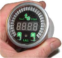
The LA1 shown uses the right hand B button to control logging
- a single press starts a logging session, another press completes it.
 Up to 255 sessions can be stored, with each session having a minimum size of 4 kbytes.
Data frames are the things that capture the logged data.
Frames are 28 bytes long, and the default logging rate is 10 frames/sec.
That's 280 bytes/second, so 1 Mbyte can save over 3,700 seconds of data (over 1 hour)
The logging rate can be varied up to around 40 frames/sec which gives 3H1 just 15 minutes of storage.
A logging rate of 1 frame/sec allows about 10 hours to be stored.
Serial PC Logging :
By default, when 3H1 has not been commanded to retrieve data from its on-board memory,
it is collecting logged data, saving it into data frames, and sending those frames out the RS232 port.
Therefore, virtually unlimited logging is possible.
Win32 and other platform Logging software is available to enable this.
|
Logging/Auto-Cal Button Operation
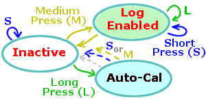
The ON-BOARD LOGGING button is located beside the right hand RED LED.
The diagram at right shows an overview of button operation -
a short button press from the inactive state is ignored,
but a medium press puts the unit into logging enabled mode.
The diagram below expands the logging function, but note that
the Auto-Cal function is entered for a long button press.
Auto-Cal is described in a section below.
|
Short, Medium & Long
- Short press is from 0.1 to 1.5 seconds.
- Medium press is from 1.5 to 4 seconds.
- Long press is greater than 4 seconds.
|
|
 slow flash (on-off every 2 seconds) = enabled for logging. slow flash (on-off every 2 seconds) = enabled for logging.
 double flash (two flashes every second) = logging. double flash (two flashes every second) = logging.
 multiple fast flashes after a long press = clearing memory. multiple fast flashes after a long press = clearing memory.
|
|
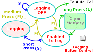
Stopping & Starting On-Board Logging
- a medium press puts the unit into the enabled state, then...
- a short press starts or stops logging - multiple sessions are possible.
- a medium press returns to the logging off state.
- a long press from the enabled clears all recorded data.
- Note: a long press from the logging off state starts Auto-Cal
which can be aborted by pressing the button before it completes.
|
Auto-Cal - Automatic Sensor Re-calibration
The major reason for having a calibration function is to initially calibrate the unit to a sensor,
and then to account for any aging of the sensor or even aging of the control unit itself (although this is minimal).
Calibration and re-calibration is the process of making the unit and attached sesor(s) read as accurately as possible.
Although we ship 3H1 calibrated to the sensor it was purchased for, calibration is required for best results,
and certainly when a differet sensor family is substituted for the sensor shipped with the unit.
We purposely manufacture 3H1 uncalibrated so it can work with a number of different sensor types with similar characteristics.
Each sensors is manufactured with slightly differently parameters and the calibration process matches the sensor to the unit.
Because Bosch sensor have a neat inbuilt calibration resistor that our units work with (see image at right),
once a sensor is calibrated, good accuracy is maintained when another sensor (of the exact same type) is substituted.
The Auto-Cal function makes it easy to re-calibrate a sensor.
In fact it almost makes it too easy!
To explain this we need to look at how calibration works.
Basily the sensor must be placed in a known concentration of oxygen (and/or fuel) and
the "gain" of the controller adjusted to match the sensor's output.
The sensor's environment is critical for it to calibrate correctly.
We choose to place the sensor in free-air which means the sensor is
directly exposed to fresh, clean, normal air that anyone could breath
(ie. it is not sitting in an exhaust pipe)
We make these assumptions about free-air :
- calibration occurs at close to sea-level pressure - lower pressures means lower concentration of oxygen.
- it is very close to having an oxygen concentration of 20.9% -
this is the basic free-air calibration assumption and this figure is surprisingly consistent.
- there is negligible additional hydrocarbon fuel content in the air - extra fuel works to lower the effective oxygen concentration.
- sensor is at an "average" humidity - high humidity reduces the effective oxygen percentage.
- sufficient time has passed for the sensor to reach a stable operating temperature.
If any of these conditions are significantly different, then, although the sensor will calibrate to some value,
it will not be as accurate as possible.
The basic risk for a sensor placed in an exhaust system, and with an Auto-Cal function,
is that re-calibration could occur with the sensor in a "dirty" atmosphere.
It is vitally important that any re-calibration occurs with the sensor out of the exhaust pipe
 Auto-Cal Operation : the actual Auto-Cal process is started by pressing the log/Auto-Cal
button for a long press - which is at least 4 seconds.
Note that this can only be done from the logging inactive state.
The red LED will start 3 short flashes which continues for about 15 seconds,
and then terminates with 6 short flashes.

During Auto-Cal:
|
- Don't blow on the sensor - the carbon dioxide from your breath will affect the results.
- Don't move the sensor nor change the battery voltage.
- Allow about two minutes of operation before the Auto-Cal is started.
- to prematurely terminate the process, press the button once - the flashing will stop.
Lastly, note that the sensor can also be calibrated using the configuration utility.
|
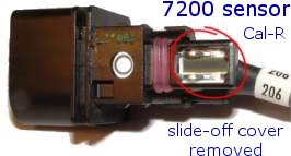
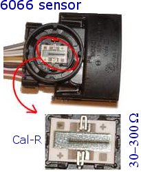
calibration Resistors : We are regularly asked about the calibration resistor.
The resistor is laser trimmed as one of the last steps of the wideband sensor's manufacturing processes.
You can see this resistor in the image above - it is located behind the circular sealed section of the 6066's connector.
The black line in the enlarged part of the image is the trimmed section - the laser burns the resistor which changes its value.
Other sensors are similar - the 7057/7200's resistor is shown circled at right.
The important thing to remember is that a calibration step is done for each sensor and
the value of the resistor is relevant only for that sensor.
It's not meaningful to measure the resistor value and then use that value for a different sensor.
Note also that, for the LSU sensor, one end of the calibration resistor is connected to
Ip (or pump current = RED wire).
The LSU calibration resistor has a guaranteed value of between 30 to 300 ohms,
but the most common values will be between 80 and 140 ohms.
|
Further Information
We update 3H1 documentation from time-to-time in response to your Feedback.
|
|




 The SVout signal [pin 1-RJ45] (pins are numbered from the left)
is described in detail above.
This connection is intended for analog displays like the
  The 6 pin RJ11 connector is designed for use with an intelligent serial display.
Its primary feature is a second serial channel called the Low Speed Serial (LSS) interface
which has a 1200 baud data rate (ie. low speed) which is adequate for most displays.
Additionally there is a duplicate of the SVout signal also found on the two RJ45 connectors, as well as a Logging Button connection, that can be brought out to an external pushbutton and used on, for instance, a dashboard. The Button signal is connected to Ground to activate it.
The RJ11 connector includes the following signals :


 The image shows the two blocks of DIP switches. They are divided into a group to set either single-ended (ON)
or differential (OFF) mode, and the other group to set the input to either use
K-type thermocouple amplifier (ON = x101 amplify) or for
0-5 Volt use (OFF = x1 amplify).
The image (the default as shipped) shows that TC1 to TC3 are set for differential & thermocouple mode,
and USR3 is set for differential & 0-5 Volt input mode.


 Up to 255 sessions can be stored, with each session having a minimum size of 4 kbytes.


