
2E0 Wideband with Display (Obsolete 2007)
|

 This model was replaced by the 3E range in January 2007.
The 2E0 was available in DIY form (electronics assembly required) as the 2E0 DIY kit.
For a current DIY model with display, check the 2Y DIY range.
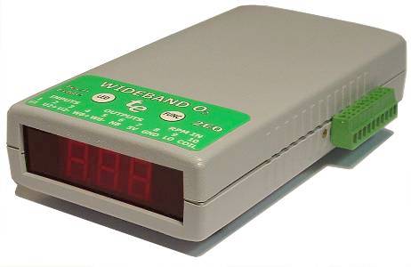
The Tech Edge 2E0 integrates a wideband Lambda unit with a 3 digit display.
It's suitable for handheld and on-dash as well as other applications
where logging is required, but where 2A0's
and 2B0's additional on-board logging memory is not required.
2E0 does not include any thermocouple inputs, and has only
2 user channels (but one is differential) and does include RPM logging.
2E0 includes the enhanced
pump cell control technology found in newer WBo2 units.
|
The 2E0 is no longer for sale (neither is 2E0 DIY kit available)
See the newer 3E1 here.
Alternatively, see the 2E0 DIY kit here (assembly skills required).
The following information is for existing users.
 | newer 3E1
| 2E0 DIY Kit
| 2E0 Connectors
| WBlin+/-
| 2E0 Fixes
Tech Edge 2E0 Features
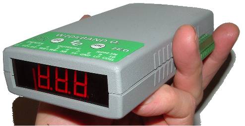
- Large & bright 3 digit display. Handheld design.
- Accuracy within 0.1 AFR (Lambda +/- 0.005).
- Works with Bosch LSU4.0/4.2 or NTK (L1H1) sensors.
- Configurable wideband 5 Volt output (12 bit accuracy).
- Two analogue inputs (one differential) and an RPM
(both COIL and low voltage) can be logged to a data collector.
- SVout output for LD01 display (10 bit configurable).
- NBsim output for existing sensor simulation (10 bit configurable).
- 11 to 19 Volt DC operation (up to 3.0 Amps).
2E0 is also available in DIY kit form
Further Technical Information
|
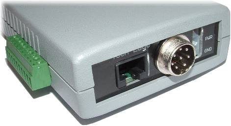
The green 10 pin removable screw terminal connector at the side (see the image at left) provides various inputs and outputs (I/O).
The label on the top of the unit describes these I/O pins which are numbered left (1) to right (10).
- Analogue Inputs are U1 and U2. Note that U2 has differential inputs with
U2+ the signal input and U2- signal GND which can be above or below real GND level.
- Wideband Output WB+ (also known as WBlin+)
is referenced to the (ground) level on WB-.
- an onboard regulator also supplies 5 Volts on 5V line,
for powering external devices such as pressure or temperature sensors.
- GND, or negative power connection.
- RPM inputs for connection to a conventional ignition coil (COIL), or the LO input
accepts a low voltage (5 Volt level) pulse input.
|
|
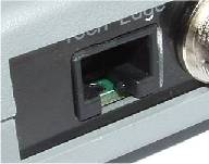 In addition to these signals, the RJ45 connector at the rear of the unit (see the image at right)
carries the following signals.
Note that some of these are duplicates (*) of signals on the green 10 pin connector :
- RS232 input/output for RS232 logging and PC maintenance (Rx, Tx & GND pins 2, 3 & 5).
- WBlin(+)*, the single-ended linear wideband output (pin 4).
- SVout, the programmable output (for LD01, etc. pin 1)
- NBsim*, the programmable narrowband output (pin 6).
- 12 Volts, current limited for a display (pin 8).
- GND* or negative power connection (pin 5).
|
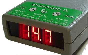
Inbuilt LED Display
The domed LED and FUNC buttons, on the label, control the display.
clicking the LED button cycles through a four predefined brightness levels so the unit can accommodate daytime use on a
dashboard and lower brightness levels for night time or indoor usage. The FUNC button swaps the display between AFR and Lambda display modes.
The status and error messages shown on the display are described below.
Software
The 2E0 unit is software compatible with the other version 2.0 units and calibration, configuration
and logging software is available.
|
2E0 Connection Overview
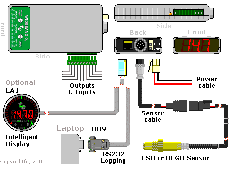
The image at left shows various parts (highlighted in blue in the text) of 2E0 and
how 2E0 is connected to other WBo2 wideband components.
Note: some JavaScript pop-up images of parts are available.
Clockwise from the bottom right, the LSU
(UEGO support may be offered later)
sensor is connected via the sensor cable
(comes in various lengths for different applications).
The sensor cable's
circular 8 pin connector mates with the 2E0 unit.
2E0 needs a source of power provided by the two pin power cable.
On the back of the case are an 8 pin (RJ45) connector for PC RS232 connectivity (config & logging)
and for optional connection to an intelligent display.
The top of the case has two buttons, with the left LED button controlling the displays brightness
and the right FUNC button toggling between AFR and Lambda modes.
The side of the case carries a 10 pin green unpluggable connector with voltage outputs and various logging inputs.
Immediately to the left of the green connector is the AMBER heater LED.
The left case end holds the large 3 digit 7 segment display.
The red status LED of other WBo2 models is replaced by the right most decimal point of the display.
Each connector and associated inputs & outputs are described in detail below.
See also the brief connector summary.
|
2E0 Technical Information
Technical Overview
| Outputs
| Inputs
| Jumper-shunts
| LED Diagnostics
| Logging
The 2E0 unit, without cables, weighs less than 220 grams.
The main case measures 150 x 80 mm with height of 30 mm.
The connectors at the back and side protrude less than 10 mm.
Sensor, power and display cables are compatible with the other WBo2 units
but the green pluggable logging & output connector is assigned specially.
The connectors are shown in the images below.
|
Side of 2E0, Y4.
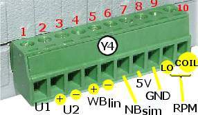
|
Back of 2E0, Y1, Y3 & Y2.
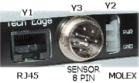
|
Click on each image to obtain a schematic view of the connectors
or see the brief connector summary.
2E0 Outputs = WBlin+/-, SVout, NBsim & RS232
As 2E0's major function is to measure AFR (or Lambda), the unit provides three (3)
software configurable 0 to 5 volt outputs
(WBlin, SVout & NBsim) that can be mapped to the currently sensed AFR.
As well, an RS232 data stream provides digitally precise information on sensed AFR and all logged inputs.
These outputs are described in detail in the following paragraphs.
for example: Pin 3/Y1 refers to pin 3 on the 8 pin RJ45 connector Y1.
WBlin+ Pin 5/Y4 & WBlin- Pin 4/Y4 Wideband Output
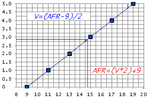
The most accurate of the 3 voltage outputs is WBlin which is generated by a 12 bit DAC
using a 65 word lookup table (with linear interpolation).
A special feature of 2E0's WBlin is what we have called a differential output
which is designed to reduce the amount of noise and possible voltage offset errors seen by a device connected to WBlin.
The WBlin differential output is described fully here.
WBlin can be re-programmed using the Config utility
to cover any part of the AFR range from Lambda = 0.6 to free-air and 0 to 5 Volt output.
Note that pin 4/Y1 (ie. pin 4 of the RJ45) also carries the WBlin+ signal,
but remember that the WBlin-GND shunt (see details)
should be installed if this single ended output is used instead of the differential +/- output.
The default linear wideband output mapping is shown in the image at right.
To convert the default WBlin voltage to an AFR simply multiply the measured voltage by 2
and add 9. This is shown in the graph at left. The advantage of a linear output
is that it's easy to write a conversion function from the wideband voltage to AFR.
|
As well as WBlin the SVout & NBsim outputs are available.
They use a 10 bit PWM circuit which is less accurate (WBlin is 12 bits) and slightly noisier too.
Both outputs can be re-programmed using the Config utility.
SVout Pin 1/Y1 (Pin 1 on RJ45) Compatibility Output
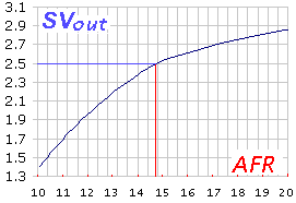
To generate SVout, the processor uses a 65 word lookup table with linear interpolation.
It converts the normalised pump current (Ipx) into a 10 bit value representing SVout.
A hardware PWM (Pulse Width Modulation) pin on the processor generates the actual SVout voltage.
SVout is compatible with the Vout signal from the original
oz-diy-wb unit (and the 1.5 unit's Vwb).
It can be used to drive the analogue LD01 display (or the older 5301 if you change its connector).
Note that the 12 bit WBlin can be re-programmed to use the SVout table,
so if you're not using WBlin and you want a more accurate SVout voltage,
you should consider reprogramming WBlin.
Remember however that SVout covers the full range of full-rich (Lambda=0.6) to free-air, the voltage range is small (less than 3 Volts)
so measuring resolution is reduced compared to using a smaller AFR range over a larger voltage range.
The default SVout, shown at right, varies between about
1.0 Volt for a very rich mixture (Lambda=0.6 or AFR=9), to 2.50 Volts
for a stoic mixture, and to 3.1 Volts for a lean mixture (AFR=25).
In free-air the SVout should be exactly 4.00 Volts when the unit has been free-air calibrated correctly.
The default AFR vs. SVout relationship is shown in the Vout table/graph page.
The analogue Vout is a continuously available signal that may be logged with a high speed logger.
We recommend at least a 10 bit converter for best accuracy.
|
NBsim Pin 6/Y4 Simulated Narrowband Output
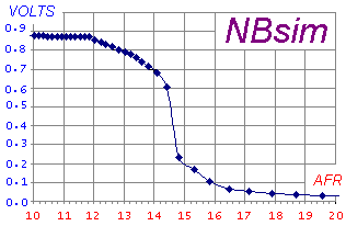
A synthesised narrowband (NBsim) voltage is produced by the onboard microcontroller
using a 10 bit A/D PWM converter (with single pole filter), and a 65 word lookup table. Linear interpolation improves lookup accuracy.
The full 0 to 5 Volt output is available, but restricting the output to 0 to 1 volt reduces the number of possible steps to around 200 (~5 mV per step).
As well as pin 6 of the green connector (Y4),
pin 6/Y1 (ie. pin 6 of the RJ45)
also carries the NBsim signal.
The NB output is designed to be compatible with
the raw output of a Bosch LSM-11 sensor. Refer to this
eXcel spreadsheet
for the graph of the default NBsim vs AFR.
As NBsim can re-programmed it is possible to do a number of
interesting things such as fooling the engine's ECU (if equipped with a NB sensor)
into running richer or leaner than it would do otherwise.
|
RS232 Rx Pin 2-RJ45 & Tx Pin 3-RJ45 Transmit/Receive
|
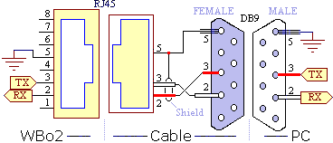
The 2E0's RJ45 connector (left black 8 pin connector) carries RS232 and other signals.
The unit transmits logged data on its Tx line [pin 3 - RJ45] and
receives commands (from PC or display) and code updates from a PC on its Rx line [pin 2 - RJ45].
The diagram at left shows the wires within the cable and also the connections at each end.
Note the pin names change from left to right - the WB unit's Tx pin transmits to the PC's Rx pin (and vice versa).
[pin 5 - RJ45] is the shield for the Rx and Tx data lines as well as being the return data path.
|
WBo2 to PC cable
Here's an image of the actual RS232 cable for connection between a PC and the WB unit.
The cable is used for either logging to a PC, or for re-flashing its code (under control of a PC).
If you need to extend the cable then a standard straight through male-female DB9 extension cable should be used
(ie. not a cross-over or null modem cable).
|

|
Other RJ45 Outputs - SVout,
NBsim,
WBlin+,
GND &
Vbatt
|
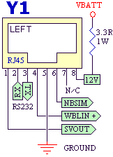
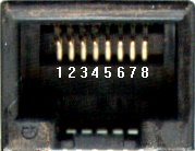 The SVout [pin 1],
WBlin+ [pin 4] &
NBsim [pin 6]
signals are all described in detail above.
The SVout signal is intended for analogue displays like the LD01 and
those displays will also use Vbatt & GND described below.
The RJ45 connector signal names are shown at right.
A fused, protected and partially filtered battery voltage Vbatt
is available from [pin 8] (right most RJ45 signal).
This output is provided to power other devices such as the LA1 display or
the LD02.
It should only be connected to devices that will draw small currents; typically less than 100 milliamps.
Excessive current consumption may cause heating of an internal dropping/protection resistor.
A ground GND point [pin 5-RJ45] is provided as a return for the RS232 and Vbatt connections.
Note that there is one unconnected output (N/C = No Connection) on pin 7 of the RJ-45 connectors.
|
2E0 RPM Input
Tacho Input - RPMcoil (Pin 10/10) & RPMlo (Pin 9/10)
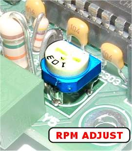
2E0 has a single RPM channel that is captured for logging.
Two inputs are provided, one for direct connection to a COIL (or a Tach signal
as generated by some vehicles) and another for a lower voltage "logic level" signal
as is generated by some sensors. Only one of the RPM inputs can be used at one time.
The image at right (click to enlarge)
shows the location of VR1 inside the 2E0 case.
VR1 can be adjusted to reject high frequency noise signals that sometimes interferes with RPM capture.
The RPM COIL input [pin 10/10] normally connects to the wire going between the points and the COIL.
On vehicles that have electronic ignition and a distributor,
you would connect to the point between the transistor switch (or ignition amplifier) and the coil.
The COIL input should never be connected to any voltage larger than 12 Volts or damage to the WBo2 unit may result.
The RPM Lo input [pin 9/10] can be connected to any lower voltage signal
that produces a 5 volt pulse at some small multiple of the engine's revs.
Unfortunately the loading (low input impedance) of the Lo input sometimes makes it infeasible to connect
to sensitive circuits such as an inductive crank angle sensor.
|
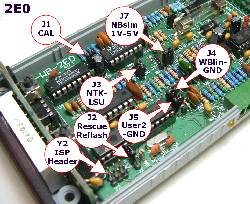
|
2E0 Jumper-Shunt Locations
The following sections describe how hardware options are set using on board jumper-shunts (often just called jumpers).
These shunts are :
- J1 - Calibration jumper (always ON - not described below,
shown here).
- J2 - Rescue-Reflash jumper (must be OFF except when rescue re-flashing).
- J3 - NTK-LSU selection jumper (as for the NTK or LSU sensor used) - Note: check for NTK firmware support.
- J4 - WBlin-GND jumper (on to select GND reference, more info. here).
- J5 - User2-GND jumper (on to select GND reference) for single ended inputs.
- J7 - NBsim 1V-5V jumper to scale NBsim output by 1/5 (in the 1V posn.).
- Y2 - ISP Header for programming (factory use - not described below,
shown here).
Click on the image or here for an enlarged popup of the jumper-shunt locations.
|
Reflashing - Firmware Updates [J2]
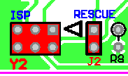
As mentioned in the software section, the
reflash utility is used to update the 2E0's firmware (or operating software).
The rescue jumper is not normally required to be used.
The image at right shows the location of the rescue-reflash jumper-shunt.
The normal position for the jumper-shunt is with the shunt on one leg ONLY (ie. when the unit is NOT being re-flashed)
is shown in the popup.
Place the shunt over both pins to enable the rescue re-flash mode.
|
NTK UEGO & Bosch LSU Support [J3]
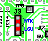
The 2E0 has hardware support for both the NTK UEGO sensor (L1H1, L2H2 & related models)
as well as the Bosch LSU sensor (all LSU 4.0 & 4.2 models).
Go here for more information on the sensors supported by 2E0,
but remember the sensor's actual connector may be different between otherwise compatible sensors.
To change the sensor between UEGO (NTK) and LSU (Bosch), two things must be done:
- Change the hardware which entails :
- Changing the 2E0-to-sensor cable to match the new sensor (see cable information here).
- Set J3 jumper shunt for either the NTK or LSU.
Click on the image for a popup photo-image of the shunt settings.
- Change the firmware by re-flashing 2E0 with the latest firmware for that sensor.

Be very careful to match the J3 jumper shunt's position correctly as using the NTK setting with an LSU, or vice versa,
may damage the sensor or the 2E0 control unit. This warning is particularly relevant if you swap from LSU to NTK.
The J3 shunt is near the centre of the PCB and it's quite clear which is the NTK or the LSU jumper side to use.
|
WBlin - GND Reference [J4]
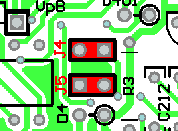 This shunt controls the WBlin+ output's reference input (WBlin-).
This topic is discussed here.
It is important to note that incorrectly setting this jumper can result in either:
- Excessive WBlin+ noise (mostly heater switching transients at 30 Hz) on WBlin+
(with shunt installed = ON when it should be OFF and WBlin- goes to the input amp's GND).
- floating WBlin+ output that can exceed 5 Volts or go below 0 Volts
(shunt is OFF when WBlin- is left floating).
Note that if J4 is OFF, the effect of the J4 shunt can be reproduced by wiring together pin 2/6 & 3/6
(ie. WBlin- to GND of the green connector).
This obviates opening the case to access J4 (but make sure J4 is off when you need it off!).
Click on the image for a photo-image popup.
To park the J4 shunt in the OFF position, place it on just one leg (as the other shunt is shown).
|
User2 - GND Reference [J5]
 The J5 jumper shunt controls the User2 differential input found on
the green connector Y4.
When J5 is ON (default) the USER2 negative input is grounded and
the differential input becomes a single ended input referenced to GND, so only a single wire is required to the USER2+ (Y4 pin2) input signal.
With the shunt OFF the input becomes differential and two wires are needed to connect to the signal source.
Note that if J5 is OFF, the effect of the J5 shunt can be reproduced by wiring Y4 pin 3 & Y4 pin 8
(ie. USER2- to GND of the green connector) together with a short piece of wire.
This obviates opening the case to access J5 (but make sure J5 is off when you need it off!).
See here for a popup schematic of Y4's USER2 input.
To park the J5 shunt in the OFF position, place it on just one leg.
|
NBsim 5V-1V [J7]
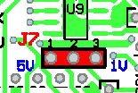 The J7 jumper scales the NBsim output from the normal 0 to 5 Volt output into a compressed output from 0 to 1 Volt.
This can be useful to get the full 10 bit NBsim resolution over just 1 volt (corresponding in theory to steps of around 1 mV rather than 5 mV).
Remember that the NBsim output can be re-mapped to emulate other wideband unit's output
(such as the Autronic's AFR output of 10 to 30 for Voltages from 0 to 1).
|
Operation of the LED Display, Heater LED & Status Dot
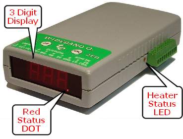
In addition to the 3 digit display at the end of the case,
beside the green connector there is a single amber heater status LED.
Additionally, the right most decimal point (the Status DOT) is used to display operating status as described below.

|
When the unit first power up, the Tech Edge logo display should be seen for about two seconds.
This gives an indication that power is on and the processor is working.
|
|
|

|
Normally the unit will then go into heating mode with the screen shown.
This should last for 20 to 30 seconds.
Longer periods may indicate the sensor is being cooled excessively, or the battery voltage is relatively low.
|

|
If the sensor has a major mechanical failure, or the sensor cable is unplugged (or damaged), then the Heater Open error may be displayed.
|

|
If the sensor cable is shorted (or the sensor damaged), then the Heater Short error may be displayed.
|

|
If the control unit's heater driver FET is found to be non-functional then the Heater FET error may be displayed.
|

|
A more common possibility is when the battery voltage is so low (less than approximately 10.5 Volts) the unit cannot power the sensor.
In this case the Battery Low condition is displayed. If this occurs regularly then check your wiring or power take-off point.
|

|
Similarly, when the battery voltage is too high (above about 19.5 Volts), the Battery High display is shown.
In both these battery conditions, the amber LED on the side should be very briefly flashing on, but will appear dim.
This condition can be caused by a faulty alternator or loose battery terminals and should be investigated immediately.
|

|
During normal operation when the sensor detects a very rich condition that it cannot give a reliable AFR for (around Lambda=0.6 or richer)
the Rich indication is displayed.
|

|
Similarly when the sensor detects a very lean condition (around Lambda=3.0 or greater)
the Lean indication is displayed.
|

|
Normal operation will produce either the Lambda or AFR display.
The AFR display with two digits to the left of the decimal point is shown.
|

|
Pressing the FUNC button changes to the Lambda display as shown.
There is one digit to the left of the decimal point.
Holding down the FUNC button for at least 6 seconds will force the current display to become the default power-up mode.
To show the mode has been changed, the display will briefly display EE.
|

|
Other displays that can be shown are the "OFF" screen when Test Mode 0 is entered, or ...
|

|
... the "CAL" screen when Test Mode 2 is entered.
For more details of these modes see the DIY kit section.
|
Diagnostics from the AMBER Status LED & Red Status DOT
Apart from the above status and error conditions noted, the Heater Status LED and the Red Status Dot
(right most decimal point) can provide extra information about transient conditions.
Normal Operation :
The unit should always have a brightly LIT AMBER LED that flickers at 30 Hz (just perceptible).
The intensity of the AMBER flicker will give some idea of how much power is being used to maintain the heater's temperature.
The Red Status Dot should NOT be on or flashing (unless the unit is
heating and in this case it will not be flashing)

PID Unlock Condition :
It's possible for transient conditions to cause the RED Status Dot to flash ON briefly.
As long as the AMBER LED remains on,
then this is an indication of a PID unlock condition.
On WBo2 there is are two PIDs - a heater PID and a wideband PID.
From firmware revision 0848 ...
- The Heater PID unlock is indicated by a single flash of the Status Dot.
- The Wideband PID unlock is indicated by a double flash of the Status Dot.
A PID unlock is not necessarily an error, but it does indicate either :
- Heater PID Unlock - very rapid changes in heating or cooling of the sensor, and/or
- Wideband PID unlock - rapid changes in the ambient air-fuel ratio (may occur under very rapid changes in throttle position).
If a PID unlock condition occurs without an explanation then it
may be an indication of an intermittent somewhere in the wiring, an ageing sensor,
or an indication the sensor is placed where it gets too hot or is cooled excessively.
Both the LD02, LA1 and the TEWBlog logger indicate these conditions.
Serial Logging & Software
2E0 does not store data on-board like other WBo2 models.
But a serial data stream (described here) is available to be logged to a PC or other RS232 device.
Logging software for Win32 and other platforms is available right now.
|

 This model was replaced by the 3E range in January 2007.


 The SVout [pin 1],
WBlin+ [pin 4] &
NBsim [pin 6]
signals are all described in detail above.
The SVout signal is intended for analogue displays like the


