T15 Logger Technical Guide

|
The T15 Logger is a simple data collector with a pseudo serial (almost true RS232) interface.
In its standard form it has three 0 to 5 Volt analogue inputs and an RPM or pulse counter input.
T15 is designed to be a DIY (Do It Yourself) device.
The design is based on the inbuilt logger of the now superseded
TE-WB (rev 1.5)
wideband unit.
The design is not intended to be the last word in accuracy,
but rather an exercise in functional simplicity
with the ability for on-board expansion.
These notes and schematics are to help you understand how the Tech Edge T15 logger works and is built.
We also hope it will inspire you to think of alternate uses for the device.
Please note that all images and text are
Copyright © Tech Edge Pty. Ltd.
|
Schematic Guide
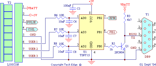
Logger connector, Microcontroller & RS232 output

The Green logger connector allows you to connect 3 user (0-5 volt) inputs,
and an RPM input (either low voltage pulse from an ECU or similar,
or a high voltage pulse from a Kettering coil ignition).
Power (VBATT) and Ground is also available
as well as +5 volt output (~100 milliamp) for conveniently connecting to external circuitry
The Atmel® Tiny15 microcontroller has custom firmware which performs analog to digital (A/D)
conversions on the logged inputs, as well as timing the RPM input.
Recorded values are packed into a data frame
and sent out on the PB0 pin driving NPN Transistor Q1 which acts as an RS232 output.
Note that the resultant RS232 data levels are between 0 and close to VBatt
which, although is not true RS232, should work with most RS232 receivers.
Note: this logger differs from TE-WB (rev 1.5) as follows:
Wblin output is replaced by xxxx
The Vwb input is replaced by general purpose input USER 2
|
5 Volt & 12 volt Power Supply

Reverse polarity protection to the unit is provided by diode
D1 (1N4007), while Zener D2 (1N4746A) provides transient suppression. C1 through C4 filter and suppress electrical noise
around the 5 volt 7805 (U3 TO220) regulator. Diode D3 protects the
regulator from shorts across the battery input.
At the left is shown the ISP header for In-circuit System programming.
|
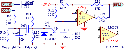
RPM, Schmitt Trigger & Spare Op-AMP (with prototyping area)

The RPM pulse train input is taken from either the PULSE or COIL input of the Green 8 pin connector.
Different signal conditioning for each input results.
C12 is a DC blocker on the low voltage input. D4 removes negative voltage excursions.
U2B is a Schmitt Trigger to clean up the RPM pulses before being sent to the microcontroller.
The T15 logger has a prototyping area (a grid of plated holes & power and ground traces) and a spare op-amp.
This can be used to create for shaping or amplifying input voltages,
or even producing an output voltage (for example filtered PWM) from the microcontroller (use the ATtiny15's unassigned PB1 output).
|
|

|
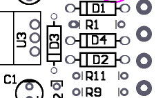
Designation Overlay
This is the T15 overlay showing the component designations (R22, C33, etc.) used on the PCB.
Click on image to view the complete overlay, or
here for a popup.
|
Constructed PCB images
These images should help you work out where all components go.
Here's the T15 PCB with most components soldered.
Note the DB9 connector is soldered on as an edge-mount and if the white end panel for the grey case is used
then it must first be drilled/routed out
before the DB9 is soldered to the PCB.
Note also the electrolytic capacitors are laid flat.
Click on image for a enlargement, or
here for a popup.
|

|
Parts List
Resistors are shown in ohms and an R (=1), k (kilo=1000)
or M (Mega=1, 000, 000) indicates both the multiplier
and the position of the decimal point. Examples are :
| 100R |
100 ohms |
| 22k |
22 k ohms, or 22, 000 ohms |
| 1M |
1 M ohms, or 1, 000, 000 ohms |
| 2M2 |
2.2 M ohms, or 2, 200, 00 ohms |
| 4R7 |
4.7 ohms |
| 0R22 |
0.22 ohms, or 220 milli ohms |
Capacitors are measured in micro Farads (μ = Greek
mu = 10-6 F), nano Farads (n = nano =
10-9 F), and pico Farads (p = pico = 10-12
F). If the value is not clearly shown in μF then it will normally be measured in
pico Farads (pF) in the form of vvm where
vv is the value and m is the multiplier as a power
of 10. Examples are :
| 47 μF |
47 micro Farads (clearly printed) |
| 100 |
10 pico farads (pF), 10 -> value, multiplier -> 0 |
| 471 |
470 pico farads (pF), 47 -> value, multiplier -> 1 |
| 474 |
47 0000 pico Farads (pF), or 470 nano Farads (nF), or 0.47
μF
|
Other common values are : 105 = 1.0 μF (1000 nF, or 1, 000, 000 pF),
104 = 0.1 μF (100 nF, or 100, 000 pF), 103 = 0.01 μF (10 nF, or
10, 000 pF), 102 = 0.001 μF (1 nF or 1, 000 pF), 101 = 0.0001 μF
(100 pF), 100 = 0.00001 μF = (10 pF)
Resistors in beige or brown (generally) have a tolerance of 5%, and resistors
in light blue or green have a tolerance of 1% and the two types should not be
mixed. Capacitors are shown in μF (micro Farad), nF (nano Farad) and pF (Pico
Farads).
Semiconductors
| 1 |
ATTiny15 |
U1 |
Atmel AVR, with modified 1v5 firmware |
| 1 |
LM358 |
U2 |
dual op-amp package (one op-amp left spare) |
| 1 |
7805 |
U3 |
TO220 5V Regulator |
| 3 |
1N4007 |
D1, D3, D4 |
| 1 |
1N4746A |
D2 |
| 2 |
2N3904 |
Q1, Q2 |
GP NPN |
Resistors
| 1 |
10R 5% |
R1 | This may be substituted with a smaller value ie. 3R3 5% |
| 1 |
1K 5% |
R5 |
| 1 |
1K5 5% |
R11 |
| 2 |
2K2 5% |
R15, R17 |
| 2 |
4K7 5% |
R3, R14 |
| 6 |
10K 5% |
R6, R7, R8, R10, R12, R13 |
| 1 |
22K 1W |
R9 | This may be substituted with a 15K 1W |
| 1 |
47K 5% |
R16 |
Capacitors
| 3 |
10nF |
C6, C7, C8 |
| 2 |
56nF |
C9, C11 |
| 4 |
100nF |
C2, C4, C5, C50 |
| 1 |
1μF |
C10 |
| 1 |
10μF |
C10 |
| 1 |
100μF |
C1
|
IC Sockets
Connectors
| 1 |
DB9 male socket |
Y1 |
| 1 |
8 pin green in-line plug |
Y2-M male PCB mount |
| 1 |
8 pin green in-line screw terminal socket |
Y2-F mating female part |
| 1 |
2x3 pin 0.1" male header |
Y3
|
Mounting
| 1 |
Grey ABS Plastic case (top & Bottom, 4 screws) |
| 2 |
case ends (grey plastic) |
| 1 |
M3 bolt (for TO220 to PCB) |
| 1 |
M3 nut (for TO220 to PCB) |
| 2 |
M3 star washers (for TO220 to PCB)
|
Changes/Modifications
More information will be added as it becomes available ....


