
WBlin+/- Explanation & Issues
Apart from our first WBo2 (2A0) unit, all Tech Edge
wideband products have "differential"
WBlin+ and WBlin- output pins.
This feature can be used to good advantage to reduce the effects of noise and voltage offsets
that can be present in an automotive measuring situation.
Most units are shipped with this feature disabled because we have found many people don't understand how it works.
This technical note explains how the feature works and how you can use it.
If it looks too complicated then scroll down to the hookup example section,
but we suggest you read through this to understand how WBlin+ and WBlin- can enhance your WBo2 usage.
Remember that there is software to Configure WBlin outputs.
WBlin Quick Overview ... WBlin- is an Input!
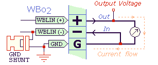
The wideband linear output voltage appears at the WBlin+ output pin (+ in diagram).
The GND pin (G in diagram) is also important when using WBlin+ because
any current drawn from the WBlin+ pin must return via the GND pin.
The WBlin- pin (- in diagram) is not an output
but a reference input for the WBlin+ output driver.
Within reason, small voltages, either positive and negative, fed into the WBlin- pin will be added to the WBlin+ output,
and this allows small offset voltages between WBo2 and the measuring device
(ECU, logger, etc.) to be automatically factored out.
Because WBo2 uses up to 3 Amps of current, when it is operating normally, the GND
point WBo2 sees may be higher than the GND point seen by the measuring device.
On the other hand, if a high current device uses WBo2, then the ground voltage difference may be reversed.
As described below, this difference between WBo2 and the device can be factored out
by correctly inter-connecting WBo2 and the other device.
The WBlin+ output can drive just a few milli Amps of current and the current is limited
by a 100 Ohm resistor so the maximum shorted current is 10 mA per volt of output,
but the output op-amp will itself limit the current before this point is reached.
Plan on using no more than 5 mA of current which means the
input impedance of your device, as seen by the WBlin+ output, should be higher than 1 kOhm.
This means that many moving coil voltmeters, can be directly driven.
Tip : Always remember that :
- WBlin is the most accurate of the voltage outputs (usually a 12 bit DAC).
- WBlin- is a high impedance input that is used to offset the WBlin+ output.
- Any current drawn from the WBlin+ output returns via the GND point.
- Check the internal WBlin-GND shunt - it is usually in place when you buy WBo2.
WBlin +/- "Differential " Outputs
First, an explanation about the "differential" output name.
We called it that because many better quality data loggers have differential inputs
and to indicate what we're trying to do, we hijacked the name
.
Technically speaking our differential output can better be described as output (WBlin+)
with a ground reference input (WBlin-).
What! our output is really an input? Well, yes.
To find out what's happening, first we'll look at the problem we're trying to solve.
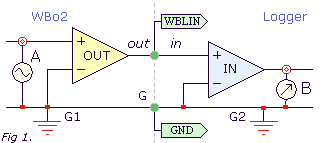
The image (fig 1. at right) shows the OUTPUT buffer in your WBo2 unit (left of the dotted line).
It is connected to a Logger (or recording device) with an INPUT buffer stage.
The central green dots represent the WBLIN or wideband output pin,
and the GND is the ground level common to both WBo2 and the logger.
The left circle with a wave symbol represents the voltage at A generated by WBo2 (this will be some value between 0 and 5 Volts).
The right circle with an arrow represents the voltage measured at the B point (with a voltmeter or by the device itself).
Ideally the measured voltage (B) is the same as the generated voltage (A).
The problem is that in any real world installation there will be small voltage differences between the two GND points G1 and G2.
Why, and what effect will this have? ...
|

In any real vehicle current flows through the vehicle's body (refer fig 2. at left).
Any conductor, including the vehicle body, has a certain resistance R
that can be measured between two points (say G1 & G2).
The R will produce a voltage difference V when current I flows.
Note: V = I/R according to
Ohm's law.
It's important to note that the current between G1 & G2 doesn't need to be passing into G1 or out of G2,
but currents from other parts of the vehicle can cause a voltage difference between G1 & G2.
How does this affect us? ...
|
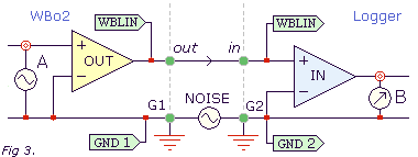
To see what can happen, first we divide the green dots (from fig 1. above), representing the Input/Output & GND,
into distinct input and output points.
We also split the G point into GND1 and GND2 points representing the GND
at the WBo2 out (G1) and at the logger in (G2).
Lastly, we add a voltage source between G1 and G2 points (see fig 3. at right).
This source generates a NOISE voltage.
So, what's the problem? ...
Although the out & in points are at the same voltage,
the NOISE voltage means the voltage between out and G1 is not the same as between in and G2.
In fact the voltage measured at B = voltage generated at A + NOISE.
What can we do to get more accurate measurements? ...
|
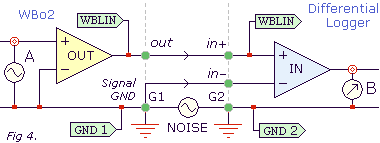
Better quality loggers have differential inputs designed to avoid noise and ground loops.
They will have In+ and In- input pins to indicate that they log
the difference between the + and - voltages.
The image (fig 4. at left) shows how the new In- input of the logger is connected to the existing G1 point.
Note that it's very important that In- is connected as close as possible to WBo2's signal GND
because WBo2 itself generates internal noise that can be seen between the signal and power GND points.
So, what if you don't have a differential logger? ...
|
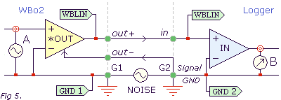
One solution is to use the logger's Signal GND (G2) input point as a Reference Input (out-),
and with the aid of a special op-amp circuit, raise or lower the out+ signal to compensate as out- changes.
The image (fig 5. at right) shows this.
In practice, this circuit works quite well when there's electrical noise and when the
out- input is terminated correctly.
But there are some restrictions.
The out- input may go below the GND1 voltage, so that the *OUT circuit must be able to also go below GND1.
This implies the *OUT circuit's -ve supply must be powered from a negative voltage with-respect-to (WRT) GND.
Similarly, as out- can have a positive value, the *OUT circuit's +ve supply must be powered from
something more positive than WBlin's maximum positive voltage (ie. > 5 Volts).
|
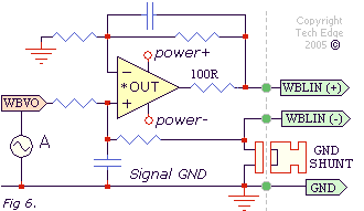
The image (fig 6. left) shows a practical implementation of the above circuit that we have dubbed the "differential output"
But we have added one important feature, the GND SHUNT (a shunt is also knows as a jumper).
The GND shunt is installed by default to ensure the ground reference input
WBlin- is not left floating.
Remember that WBlin- is the reference for the WBlin+ output.
If left unterminated, WBlin- could float above or below the GND point and
cause the WBlin+ output point to also float up and down (as measured with-respect-to the GND reference).
In the worst case, with the shunt unconnected and WBlin- floating,
the WBlin- input could add noise to the output rather than
remove noise as it was designed.
|
WBlin +/- Hookup Examples
These diagrams show WBo2's WBlin+/- & GND connected to external devices such as loggers, ECUs, etc.
The WBo2 connections (left) are shown in green
(+, -, & G)
and the logger (right) in blue
(I, +I, -I & G).
The input I is single ended and +I & -I are differential inputs.
Although the default connection works, removing the jumper can result in better performance.
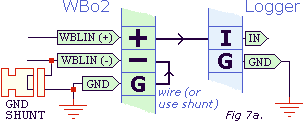
 A. The default WBo2 configuration for WBlin+/- is shown in the image (fig 7a. at right).
This configuration is a single ended output with GND return.
The internal shunt (ie. jumper) is ON so that WBlin- uses the WBo2 GND point as a reference.
This configuration suffers from poor noise rejection,
but avoids the possible situation of an unterminated WBlin- picking up noise.
To minimise noise, keep the power cables short and connect WBo2's power ground at the same point as the logger's ground.
Note that the external wire from GND to WBlin- has the same function as the shunt GND SHUNT.
|
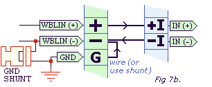

 B.The image (fig 7b. at right) is the configuration for using a differential logger.
The internal shunt (ie. jumper) is ON so that WBlin- uses the WBo2 GND point as a reference.
This configuration has good noise rejection by virtue of the logger's differential input.
It can also be used for driving a high impedance moving coil meter (+ to +, - to -).
As many loggers (this includes ECUs) only have a single-ended input, this configuration may not be possible,
but see the next example where the differential output feature is put to good use.
|
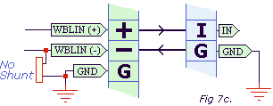

 C. The image (fig 7c. right) shows the best compromise for connecting a single ended logger to WBo2's "differential" output.
It compensates for ground noise by referencing WBlin+ to the logger's GND voltage.
Note carefully that neither shunt nor wire connects WBo2's GND point to the WBlin- input
as doing so disrupts the remote GND sensing scheme.
Note that it is very important that WBlin- is connected to GND at the logger end
as loss of that connection results in the following undesirable scenario ...
|
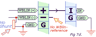
 D. The image (fig 7d. right) shows how NOT to connect WBlin-.
In this case WBlin- is left unterminated and can pick up noise.
The problem is also that WBlin- can slowly rise above GND potential and it will
bring the WBlin+ output up with it, making the WBo2 output useless.
|
Locating WBlin-GND Jumper Shunts
Refer to the product page for your controller to find where the WBlin-GND shunt is located.


