
 This document is the user's guide or operating manual for the LX1 display.
Certain programmable features described below will require the WButil configuration software to be used.
LX1 is field re-programmable
so this document may be updated from time to time with information on the latest features.
This document is the user's guide or operating manual for the LX1 display.
Certain programmable features described below will require the WButil configuration software to be used.
LX1 is field re-programmable
so this document may be updated from time to time with information on the latest features.
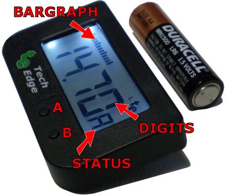
The major elements of the LX1 display are shown at right.
The two press-buttons are called the left or A and right or B buttons.
The four characters of 7-segment display are called the digits,
and the 25 element array of bars is called the bargraph.
The small 7 segment display immediately to the right of the digits provides an indication of error conditions,
and what information is being currently displayed.
 Typically the LX1 will just work - plug it into a Tech Edge
controller and it displays AFR (with stoich at 14.7).
Press the A button once and LX1 changes to the second view and shows Lambda
(stoich is 1.0).
Hold down the A button longer than 6 seconds and the current view becomes the power-up view.
Typically the LX1 will just work - plug it into a Tech Edge
controller and it displays AFR (with stoich at 14.7).
Press the A button once and LX1 changes to the second view and shows Lambda
(stoich is 1.0).
Hold down the A button longer than 6 seconds and the current view becomes the power-up view.
If you have a Tech Edge controller with on-board logging memory then the B button works to stop and start (ie. toggle) loggging to memory. Other features are described below, but remember LX1 works out of the box and most people will find no configuration will be required.

![]() The most common problem users experience is the nd,
or no data, display as shown at left.
It's caused when LX1 doesn't see data from WBo2.
You will normally never see this, but if you do,
the solution is described below.
The most common problem users experience is the nd,
or no data, display as shown at left.
It's caused when LX1 doesn't see data from WBo2.
You will normally never see this, but if you do,
the solution is described below.


A common "problem" we are asked about is the "lean" display shown at left. It is not a problem at all, the display is simply saying the controller and sensor are measuring a value where any "normal" vehicle will not be run. You will see it when the sensor is sitting in free-air, and if/when you test your controller as described here.


You could see this if you use fuels that have a stoich value much lower than 14 (this includes many alcohol fuels such as E85, methanol, etc.) The "rich" display is easily "fixed" by running a CCF file found here.
The following information relates to LX1 firmware version 0538 or above. In the descriptions of the various displays, screen names are shown in bold blue. Note: after re-configuration, some of the default behaviour detailed below may change. The default screen is the display last saved, and is initially the AFR display.
|
|
|
|
|
|
|
|
|
|
|
Releasing the left (A) button shows the currently selected screen.
The default screens cycled through are |
|
|
|
|
|
|
|
|
|
|
Sensor Heater Faults - Other heater faults that are detected by WBo2 include :
|
|
Status information is continually produced by all WBo2 units. The condition of the sensor's Wideband and heater control software and hardware (including the sensor itself) is called its PID status. When WBo2's PIDs operate outside their intended range we call the condition PID unlock. From LX1 firmware revision 0538, LX1 shows both heater and wideband PID unlock status indications. Other WBo2 documentation may refer to this condition as a PID error but it is important to note it's normally associated with a condition the WBo2 unit has no control over.
A PID unlock is not necessarily an error, but if a PID unlock condition occurs regularly without an explanation then it should be investigated. |
Config Mode & the Reprogramming Interface Adapter)
)
LX1 can be field upgraded with new firmware, and its display modes re-configured, using the LX1 interface adapter (*) shown at left. How the adapter is physically connected both to LX1, a PC, and source of power is shown at left. Power is obtained from WBo2's two pin power cable, or a 12 volt power supply is used. Click on either of the images for an enlarged popup, or for the programming adapter's schematic here. Note (*) see here for info on the old interface adapter. The FLASH.exe program can be used to update LX1's firmware, remembering that the LX1 must be in config mode for correct reflashing.
|
Rescue Reflashing)
For the very rare occasion when the LX1 seems dead (perhaps after an unsuccessful reflash, or a reflash with the wrong .HXF file) it may be necessary to perform a rescue-reflash. This requires access to the LX1's electronics. Begin by removing the four screws securing the case's back. Pull out the electronics and rotate so you see the view at left (click image enlarge) The two rescue re-flash pads will be found to the right of the LCD display, at the very edge of the board. a small piece of wire can be inserted into both pad holes, connecting them together. With the shunt in place (and the LX1 cover still removed) plug the LX1 RJ45 jack into the reprogramming interface (see previous paragraphs) and run the FLASH program - making sure to check the rescue? option. Follow the rescue reflash instruction precisely for it to work properly Note that you may have to first rescue re-flash the code in (select the Flash Only? check box), and when that has completed, remove the rescue re-flash shunt and then select the EE Only? check box and flash in the EE data (of course remembering to hold down the A button during LX1's power-up to enter the correct mode). Yes it sounds complicated, but a recure re-flash is a last ditch option that's not normally used unless drastic action is required. |
The CONF.exe program will soon provide support for LX1, and is used to change LX1's default behaviour and the display functions.
This section will be updated when the PC based configuration options (in the CONF.exe program) for LX1 are completed.
Note: this document is subject to updates ....
 Pressing the left (A) button cycles through the four possible display screens
which are numbered 0 through 3.
While the left (A) button is depressed,
The number of the screen that will be shown next is
displayed in the left digit position - as shown at left.
Pressing the left (A) button cycles through the four possible display screens
which are numbered 0 through 3.
While the left (A) button is depressed,
The number of the screen that will be shown next is
displayed in the left digit position - as shown at left.
 It's possible to change the default screen so this screen is presented each time LX1 is powered up.
First, select the screen you want to be displayed by cycling through the displays,
then press and hold down the left (A) button for at least 4 seconds.
One of the 4 possible screens at left will show, for as long as the button remains depressed.
It indicates the screen number programmed as the default screen.
Note: the next screen number is displayed during the
4 second wait until the default screen number is programmed, ignore this!
It's possible to change the default screen so this screen is presented each time LX1 is powered up.
First, select the screen you want to be displayed by cycling through the displays,
then press and hold down the left (A) button for at least 4 seconds.
One of the 4 possible screens at left will show, for as long as the button remains depressed.
It indicates the screen number programmed as the default screen.
Note: the next screen number is displayed during the
4 second wait until the default screen number is programmed, ignore this!
 Config mode on LX1 is entered by holding the left (A) button down
ONLY while power is being applied to the display.
Each time LX1 is power OFF, it will come back up in normal mode
unless it sees the button depressed during its power up cycle.
As reflashing is a two stage process (loading new code, then new EE-data),
the A button should be held down until the reflash process enters the second stage where the EE-data is updated.
Config mode on LX1 is entered by holding the left (A) button down
ONLY while power is being applied to the display.
Each time LX1 is power OFF, it will come back up in normal mode
unless it sees the button depressed during its power up cycle.
As reflashing is a two stage process (loading new code, then new EE-data),
the A button should be held down until the reflash process enters the second stage where the EE-data is updated.
)
)