|
Below are some basic warnings and a quick summary of the points in the installation guide. |
|
During operation the sensor runs at very high internal temperatures.
The sensor is manufactured from high temperature ceramic substances (modified Zirconium Oxides, etc.) and, although quite robust when used correctly, it is susceptible to thermal shock. This can occur if droplets of a liquid are sprayed onto the hot surface, as can occur during engine startup when water (that is produced during combustion) condenses on cool exhaust components. |
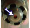
We recommend that all new users connect up their unit to power, a cable, and to the sensor to verify proper operation, before installing anywhere permanently. At this time a calibration procedure can be done and any logging or display software installed too. Please note the warning above about the sensor getting hot - we recommend you place the sensor in a ceramic/heavy-glass container or on a ceramic tile and don't leave the sensor unattended. A basic test of the sensor and controller is easily performed with a low cost butane cigarette lighter. Simply squirt unlit butane down the nozzle of the sensor. Some of the air inside the sensor will be displaced and you should see a rich indication on the logger or display. As air slowly enters the sensor, and the butane escapes, the sensor will indicate increasingly leaner conditions. Blowing sharply on the sensor when it has been filled with butane will show a rapidly changing reading, demonstrating the speed of the sensor's response. While the sensor is sitting in free-air* you will expect to see a very lean indication on the display. Free-air has an equivalent Lambda of around 208, and this is meaningless to display as such, so most of the displays will indicate LEAn or some similar indication. *free-air is what we call clean ambient air with an oxygen concentration of around 20.9% and without any combustible hydrocarbons present. |
|
As part of the confidence test, a free-air calibration can be performed. It is worth noting that all Tech Edge controllers are designed to have long term electrical stability. They do not need to be re-calibrated at regular intervals like some lesser brands. In fact (except the economy 2J range), they are designed to maintain their calibration even when a new sensor of the same type is swapped in. For best results however, we recommend you perform a free-air calibration when you first install the controller and sensor (or subsequent sensors), and perhaps 3 to 6 months later, depending on usage and operating environment. It cannot be stressed enough that a free-air calibration can only be performed in free-air. The air in an exhaust pipe can remain very different to free-air for hours or even days. Always remove the sensor from an exhaust pipe, or for an exhaust sniffer-pipe, make sure you flow fresh air through the pipe before calibration. Your breath can have an 0xygen content of 15% rather than around 21% for free air, so don't blow on the sensor during calibration. Many of the newer models have an auto-cal button (or for older controllers, newer firmware uses the logger button to also act as a free-air auto-cal button when operated correctly). Refer to your controller's documentation for how to auto-cal, or otherwise, use WButil's free-air calibration function. |
 For optimum performance the oxygen (or lambda) sensor should be carefully positioned.
This will also improve its life expectancy, and ensure trouble-free and accurate operation.
Bosch (and NTK) are careful in their specifications to spell out what must be done and what should be avoided.
For optimum performance the oxygen (or lambda) sensor should be carefully positioned.
This will also improve its life expectancy, and ensure trouble-free and accurate operation.
Bosch (and NTK) are careful in their specifications to spell out what must be done and what should be avoided.