RJ45 Splitter (+ WBlin/NBsim Access)

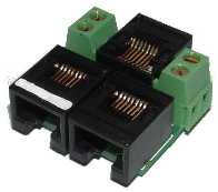
The RJ45 Splitter is primarily for use with 2A0/2A1, 2E0, and (the original) 2C0 to expand the single RJ45 (8 pin) connector into two. The splitter also provides convenient access to the WBlin and NBsim signals. The 2C0 unit (which brings out WBlin+/- & NBsim on a pluggable connector) has an additional RJ11 (6 pin) connector that carries low speed serial (LSS) data which is different to the RS232 data on the RJ45 connector.

Splitter Modifications & Checks

These issues, and the splitter, are discussed below. Note : popup images shown thus require JavaScript to be enabled.


RJ45 Splitter Details

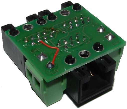
Shown at right is the splitter with the flat cable that is supplied when you purchase it. The flat cable has two RJ45 plugs at each end and is normally supplied in the ~150 mm length only.

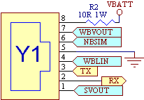
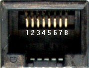
The 2A0 RJ45 connector (Y1 on the 2A0 schematics) carries the WBlin, NBsim, SVout analogue signals and RS232 I/O Rx & Tx lines, as well as current limited Power and GND. The WBVout signal is not found on all models. Other WBo2 units will have similar RJ45 pinouts. The pin numbering scheme for all units is shown at right.

The RJ45 splitter duplicates these 8 signals and provides access to WBlin & NBsim on the two 2 pin screw terminal blocks which are supplied in either blue or green colours.

Note : If you want to replace, or use a longer cable between WBo2 and the splitter, than you should be aware that the crimped-on RJ45 plug ends must be attached with the correct orientation to preserve the pin numbering from WBo2 to the splitter itself. With the flat cable shown, one RJ45 plug has the locking ear up, and the other end has it down.

RJ45 Splitter Fixes - WBlin to WB
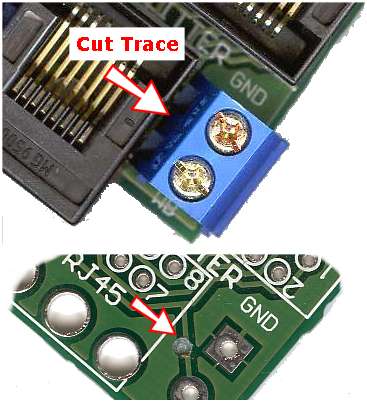


As noted above, a small number of RJ45 splitters may have been shipped with the connector marked as WB (on the silkscreen) connected to the SVout signal rather than WBo2's WBlin signal.

The fix is simple and fairly easy to perform, but first note that all splitters that have been factory modified will have an extra insulated wire under the PCB, as shown in the image at right (enlarged).

The image at left shows the first step of the modification (enlarged) where the existing PCB trace to the WB pin is cut with a Stanley® knife or box cutter, or drilled out (as is shown on the lower bared PCB) using a small twist drill.

A wire must now be added from the solder side pad marked WB to pin 4 of the closest RJ45 socket. We use small diameter wire wrap of various colours (red shown at right), and we also epoxy glue (two part 5 Minute Araldite®) to anchor the wire securely to the PCB.

Also shown at right is the modification (a cut trace on the solder side) required for simultaneous LD02 & PC logging.

RJ45 Splitter, LD02 Fixes (Simple [1] & Complex [2])

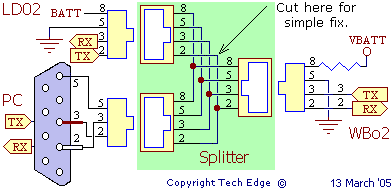
With the introduction of the digitally connected LD02 display there is now the possibility the Tx RS232 signal from the LD02 can interfere with the same signal from a PC being used to log data from WBo2. The issue is that although both the LD02 and PC can share the Tx output signal from WBo2, their own Tx outputs should not be connected as they will both attempt to drive the same signal.

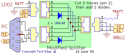
Note : Tx from WBo2 connects to Rx signals on the PC and LD02, but PC and LD02 output Tx lines are connected together at the splitter. This is shown in the schematic at left. Note also the crossover for the RJ45 to DB9 plug for the PC cable.

This situation is only an issue when a splitter is used with the LD02 and a PC at the same time. To avoid this signal conflict the two Tx signals must be separated either physically, or electrically, at the splitter. There are two possible soultions.

  1. The simple fix simply cuts a signal wire so the LD02 can't interfer with the PC's Tx line. This has the disadvantage that the logging button on the LD02 cannot function to stop and start on-board logging.
  2. A more complex fix using steering diodes solves the problem by allowing both the LD02 and the PC to transmit data to WBo2 at the same time (in general this works fine as Tx is rarely used by either PC or LD02).

Simple Fix [1] Remove One Tx Line

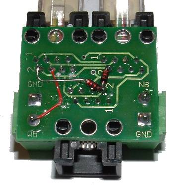
The first and simplest modification is shown in the image above right. One of the Tx lines (shown with two white lines) is cut with a sharp knife. The trace to cut is from the left hand RJ45 pin 2 (solder side of PCB). Here's another view of the mod that also shows the added WB modification noted above.


Complex Fix [2] Add Steering Diodes

This is only slightly more complex, but it does require extra components (two small signal general purpose 1N4148 diodes). A second cut is made in the pin 2 trace from the other RJ45 connector. The diodes are soldered with their bands close to the 2 designation on the PCB.

This modified splitter assembly is shown at right or here in in diagram form.

Note that since June 2005 all splitters sold by Tech Edge have been modified with the steering diodes as described.

Although we have not experienced problems with this modification, to be technically correct, the diodes should have a resistor across them of about 4.7 k ohms.