As much as we think our latest product is the next best thing since sliced bread,
there comes a time when a trusty product slips from the best seller list,
and we decide to retire it as a current product. It becomes obsolete.
It does not mean we don't support or fix it,
It just means you can't buy it from us anymore.
Note: Our older stuff appears occasionally on eBay™ (and other sites) from third party sellers (as 2nd hand items),
but we do not normally sell our own stuff that way - but we will make it clear who we are if we do.
We don't normally offer warranty on used goods but we are usually
happy to repair (using our warranty system) goods that have been purchased 2nd hand, in good faith.
Here's a list (probably needing updating as at 2011/3) of items we once sold, with the most recent retiree first (shows Year/Month of last sale).
2J1 (2010/7)The 2J1 controller was last sold mid year 2010. We offered the 2J2 controller as a replacement. More recently (January 2011) the 2J9 controller, using the LSU-4.9 sensor, is suggested as a better alternative. We retired the 2J1 because it was expensive to build with its attached cables, and small number of customers complained that its one-size-fits-all controller-to-cable was too short. In fact we have found the 2J2/9 with a separate cable is not really any cheaper to build, but it is more flexible. |
2B0 (2005/12)Identifying the 2B0 unit (shown at right) is easy although they were sold in two quite different shades of green. The 2B0 has an all white label with green lettering. The replacement 3B1's label has a predominantly black background with green lettering (as shown in the small image at left). The 2B0 also has no lettering on the case to indicate the usage of the front and rear connectors. The 2B0 started shipping in May 2004 and was replaced by the 3B1 in December 2005 although the website still showed the 2B0 for most of 2006, we were shipping the 3B1 for all 2B0 orders. We replaced the 2B0 primarily to allow us to build a replacement unit using modern surface mount construction. (thru-hole technology on 2B0). 3B1 also added an 8.192 Volt maximum output rather than 2B0's 5.0 Volts and adds a pulse (or VSS) input. Better configuration of the inputs on the 3B1 allows the selection of 1 to 6 inputs covering 0 to 5 Volts and up to 4 thermocouples. We also made small improvements to the circuitry for better stability and long term accuracy, making the 3B1 our best unit as of the start of 2007. |
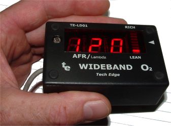
2C0 Pre-Production Prototype (2005/3)Identifying the 2C0 Pre-Production Prototype is easy, it does not have the green and black 2C0 label of the production unit shown here and at right. It simply has 3 different coloured LEDs poking through the case, and nothing on the outside to identify it as a Tech Edge product at all!. Not a lot of these units were produced and there is some errata that may be important if you have one, or are thinking of acquiring a used one. The 2C0 uses a surface mount 44 pin Atmel AT-Mega16 processor at 16 Mhz and was the third fully digital controller we designed (after the 2A0 and 2B0). The 2C0 prototype first went on sale in December 2004. LD01 Wideband Display (2005/1)This trusty workhorse was available as either a DIY kit or as a Prebuilt unit. Either way, you got a fairly robust 3 digit unit that showed only AFR (with an assumed stoich value of 14.7) and it could not display Lambda (nor stoich values other than 14.7) without changing the chip inside - we did offer a Lambda mode chip. It had a few shortcomings - although the display brightness was controlled by an LDR sensor, it was prone to strobing effects when you went under street lights that made it shine brighter briefly; its LDR filter time constant was too short. LD01's biggest shortcoming was that it connected to the wideband controller using an analogue voltage and this produced errors that could be worked around but it was never resolved to my total satisfaction. Later models (LD01b) had an added button at the side. It was the intention we'd use it to switch between AFR and Lambda however we started selling them when the updated firmware was not ready and we eventually kept selling them that way (ie. with an apparently non-functional switch). The LD01 uses a 20 pin Atmel AT-Tiny26 processor (with no crystal) directly driving the LED modules. It was designed to also be able to drive a multi-line LCD display module. Inputs for RPM and thermocouples were designed on the PCB but no code was ever written for these modes. We had the LD01's lid laser-cut and the lettering was screen printed just like the TE-5300 (see below). The LD01 first went on sale in June 2003 and was primarily designed to compliment the new 2A0 controller that went on sale the next month (July 2003). The LD01b first went on sale in May 2003 and was superseded in December 2004 by the LD02 (the last LD01b sale in January 2005). |
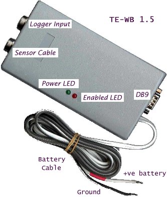
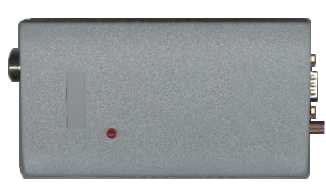
TE WB-1.5 as DIY or Prebuilt (2003/7)This model is easily recognised as it has a single red and a single green LED (2 LEDs) and also a DB9 connector at one end and two circular connectors (5 and 8 pin) at the other end. Some versions of the 1.5 unit did not have the 5 pin connector. and none had a Tech Edge label! The 1.5 unit was a major redesign, during the second half of 2002, of the original 1.0 unit. The 1.5 was available as a DIY kit or as a prebuilt and tested unit and first units sold in November 2002 for AU$150/each as a DIY kit. The 1.5 unit was superseded by the 2A0 July 2003. We took the 1.0 design, cleaned it up a little and added an (optional) 8 pin microcomputer (Atmel AT-Tiny15 with no crystal) to read the raw wideband voltage the analogue circuitry produced, and to produce a linear version of that voltage. An RS232 data stream, at 19k2 baud was also generated as well as an RPM converter and two other user analogue voltage inputs. The RS232 data stream opened the possibility of logging other engine parameters as well as AFR/Lambda. Many third party software programs were written to display and save the collected data. The biggest problem with the 1.5 unit was that it only supported the NTK (either L1H1 or L2H2) sensors. These sensor had been priced as low as US$90 in 2001 but by late 2002 and into 2003 the sensors had risen to as high as $200. Additionally, the basic sensor control was done by fairly basic analog circuitry. Heater control was better than on the 1.0 but a large measure of accuracy was lost by not keeping the sensor temperature at a precise value. There was only a rudimentary (free-air) calibration control and the linear output was via two conversions (analogue to digital and back to analogue) at less than 8 bits of accuracy. |
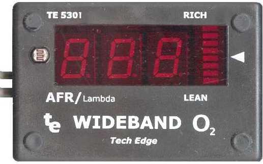
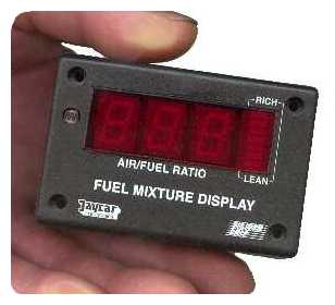
TE-5301 Display (2003/6)The 5301 wideband display was available as a DIY kit or as a Prebuilt and tested unit. The 5301 grew out of the TE-5300 (see below). Because we bought so many KC5300 displays from Jaycar, and because we had modified the circuitry, we decided to design our own PCB and DIY kit. At this time we were also making the Oz-DIY-WB (see below). Our design was electrically and software compatible with the KC5300 but we used double sided plated through boards that were more robust. Our kits also included superbright 7-segment LED modules which were much better than the Jaycar modules. The firmware was the same as the modified FMD used with the KC5300, and used an 18 pin MicroChip PIC16F84A processor at 4 Mhz. The 5301 was supplied with a second DB9 cable attached. This cable carried a 19k2 baud data stream that could be used to display the decoded wideband AFR/Lambda on a PC (or any device that could interpret the simple data stream). Not quite a year after the oz-DIY-WB became available, in September 2002, the 5301 first sold for AU$70 (as a DIY kit). A major task we had in manufacturing these kits was the laser cut and silk screened front panels. We contracted these two operations out with varying success, and it was an aspect of the unit I was never very happy about. These displays sold very well and many people teamed the 5301 display with the Oz-DIY-WB for a reasonably accurate wideband unit. |
The TE-5300 Display (2002/9)The SC FMD (see below) morphed into the TE-5300 DIY display and was Tech Edge's first DIY Wideband Display designed to work with the Oz-DIY-WB or the original DIY-WB that was also available in the USA then too. The 5300 was first described in November 2001 and the kit consisted of some additional parts added to the Jaycar KC5300 kit that we obtained from Jaycar directly in bulk. |
Silicon Chip FMD Display (not sold)This was never a Tech Edge product, but an on-line description of the Silicon Chip (SC) project called the Fuel Mixture Display (FMD). The FMD was presented in the September and October 2000 editions of SC magazine. In 2001 Silicon Chip did not have the on-line presence it currently has in 2007, so in August 2001 I presented, on-line, some of the kit information from the paper magazine. At that time I was an active member of the US based DIY-EFI list and suggested that the FMD, with some table medications, could be used as the display for a DIY project that was just getting off the ground - the DIY-WB. There is some conjecture about who owned the original DIY-WB design (and some day I'll have to write this down), but DIY-WB was the basis for Tech Edge's first product, the Oz DIY WB kit. In November 2001 I made the modified FMD available as a DIY kit, and started selling this, and the Oz-DIY WB board (see above) as a simple DIY wideband kit with a digital display readout. |
Oz-DIY WB 1.0 Controller, (2002/12)The original version 1.0 Oz-DIY-WB controller was undoubtably the worlds first affordable wideband controller produced in large enough numbers for it to have a worldwide impact. It was Tech Edge's first wideband controller and was available as a DIY kit or a pre-built and tested unit right up until December 2002 and even into 2003 when the newer/better 1.5 DIY-WB unit became available. The Oz-DIY-WB is almost exactly the same circuit as the US DIY-WB. In September 2001, as an enthusiast vehicle tuner (software engineer at the time), I tried to organise a group-buy of those original DIY-WB PCBs, and received money from around 25 like-minded Australians. The purchase fell through (this event is the subject of much debate) and I was approached by an Australian who had just done a layout of the DIY-WB circuit onto a very small double sided PCB for his own use. In return for some manufactured PCBs, the designer gave me the rights to the layout and I organised the PCBs. Everyone in that group-buy got their PCBs, and the Oz-DIY-WB controller was born. It was originally my intention, in September 2001 to produce only the 25 boards to satisfy the local demand, but many more people wanted the board and a kit of parts to go with it. People also asked if I could build these kits for them, I was available to do this, and in late 2001, early 2002, Tech Edge's commercial involvement with wideband began. By the end of 2002 Tech Edge employed 3 extra full-time people and in 2003/4 up to an extra 4 part time people. |