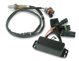
If you have a Holley Commander 950 (called the HC-950 here) then you may be interested in using various features of the HC-950 that require a wideband controller. Holley have a Wide Band O2 Upgrade Kit (shown at left). In fact it appears to be another manufacturer's wideband controller. But no matter, you can use a Tech Edge controller, and save yourself a considerable amount, as described below.
The Holley wideband unit (called HWU here) has an AFR measurement range of from 10.0 to 18.0 (assuming stoich of 14.7). The HWU outputs a non-linear voltage between ~ 0.7 Volts and 2.8 Volts over this range (see the spreadsheet link below). All Tech Edge units are programmable so it should be no problem to re-program any WBo2 unit to output the same voltage. Another, and better, possibility is to reprogram the Holley 950, using Holley's own software, to accept the default Tech Edge linear output voltage of 0.5 to 4.5 over the 18 to 10 AFR range (shown at right). This scheme has the advantage of almost twice the voltage range than the HWU and therefore reduces potential sources of error. Errors can occur in the digital to analog & analog to digital conversions required for the wideband measurement to get from the wideband unit to the ECU. |
|
As with all analog voltage measurements, it's important to avoid voltage offset errors (this topic is described here). These errors can occur when two electronic modules have small differences in their ground voltage level. A Tech Edge controller with a differential output voltage (only some early models didn't have this feature) is the best choice to counteract this effect. Although most Tech Edge controllers will work, lets assume we use the 2C0 as the sensor controller. The 2C0 has the advantage of simplicity and small size, and a simple, pluggable, 6-pin screw-in connector to make wiring simple. The image below (not to scale) shows how the 2C0 is connected to the HC-950. Wiring the 2C0's WBlin +/- to the Holley HC-950 Loom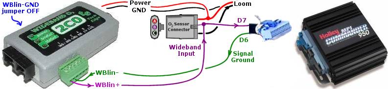
Note that the actual sensor, and cable from the 2C0 to the sensor, are not shown above. The sensor cable plugs into the back of the 2C0. A display can be plugged into the black 8 pin RJ45 connector at the left end of the 2C0. The important things to note above are that:
Changing the Holley AFR table to Match the 2C0's Output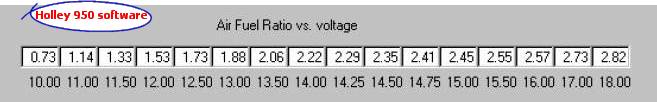
The next thing to do is set up the correct conversion table from Volts to measured AFR within the HC-950. This table appears in various HC-950 software menus, but they all look and work the same way. The table above shows the default entries when using Holley's own controller. The new entries below are simply the tabled version of the graph that appears above right. Here's a spreadsheet and graph for each table. 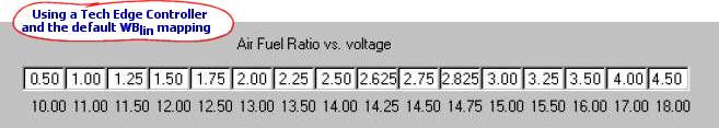
Everything is now set up. Remember to read up on how to use your wideband sensor and in particular where to place the sensor. A tailpipe sniffing position requires special measures to ensure the sensor is not over cooled and using an existing narrowband sensor bung, close to the exhaust valves, may result in overheating the sensor - see here for more info. |
Testing that the measured Voltage matches the Holley's AFR
Apart from the testing recommended in the previous link, you should also test that the voltage you can read across the WBlin+ and WBlin- pins matches the AFR vs. Voltage you programmed into the Holley software. If there is a difference a simple test is to remove the green connector from the 2C0 and feed a fixed voltage from (say) a 1.5 volt torch battery into the Wblin+ and WBlin- pins (connect Wblin+ to [+], WBlin- to [-]). First measure the voltage (it will not be 1.5 volts!) and look up the expected AFR (AFR=12.0 for 1.5 Volts) or use the formula : The Holley should see the calculated AFR - if not then check that you have indeed programmed the Holley correctly. Once you have the Holley reporting the correct AFR (make sure the voltage on the battery remains the same so you don't chase your tail!) then you can remove the battery and reconnect the 2C0. You should see that a WBo2 display (or PC) connected directly to the 2C0 should show the same AFR as the Holley is reporting. If not then make sure the wires are connected as described above, and the WBlin-GND shunt is removed (on the 2C0). Remember that an unlit butane lighter makes a good tester to provide a varying real-time signal from the 2C0 unit (as described here) More ...We're always happy to hear of people's successes and also their problems in setting up and using our equipment. See the feedback link below or contact us via the contact info below. |