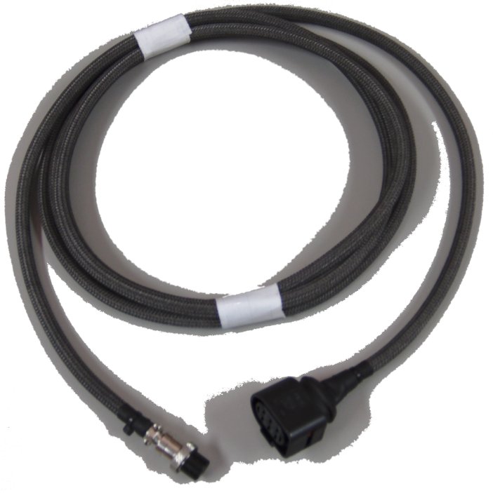
Most of our controllers use a cable from the controller to the sensor (2J1 has an inbuilt cable). The cable's sensor end has a harness connector that mates with a standard (unmodified) 5-wire wideband sensor. Possible sensor end connectors are described here. The controller end uses a circular 8-pin connector shown here.
Pre-built cable are available in standard lengths (0.4, 1.0, 2.6, 4.0 and 8.0 metres) and with various end connectors. Our cables are constructed using our own specially manufactured multi-core and selectively shielded cable. They are covered with a tough fibreglass sheath and finished with connector seals and heatshrink boots at the ends. Despite this, they should be used away from sources of heat, abrasion and mechanical vibration, and secured firmly in place.
DIY cable kits can also be purchased. Cable kits include the cable (2.6 or 4.0 m length), sheath, and the circular 8-pin connector along with heatshrink. A harness connector must also be purchased to make a cable that matches the pre-built cables described above.
|
Buy DIY Cable Kits - also requires Harness Connector KitYou can make your own DIY cable from scratch using what wires you have available. But we suggest you use our DIY cable kit to give you the unique custom-made Tech Edge shielded wire, tough and heat resistant woven fibreglass sheath, heatshrink joint covers and the 8-pin circular connector. The whole kit is not much more expensive than the 8-pin connector!Cable Kits are available in either a 2.6 or 4.0 m lengths. note: These cable kits do NOT include the harness connector that mates with the sensor. Larger image.
For NTK sensors (L1H1) ...If you are constructing the NTK version of the cable for the L1H1 sensor then see the NTK cable page, but refer to this page for detailed construction information. |

|
These paragraphs show how our older two part cable was constructed. Our newer one-part cable is described in the 2Y construction section. Go here for information on LSU connector kits used by WBo2, or go here for LSU connector & wiring; information.
|
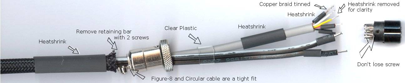
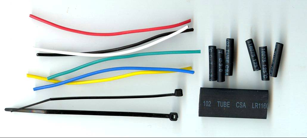
This image shows all the parts required for the circular 8 pin plug end of the sensor cable. First remove the two screws securing the retaining bar of the metal housing. The two cables can now just be threaded through the housing. |
|
Make sure all the pieces of heatshrink are in place before soldering. Leave sufficient space by bunching up the fibreglass braid, but don't twist the cables within the braid as they are hard to reseat. Be careful of prematurely heating the small heatshrink tubes with the soldering iron. |

|

|
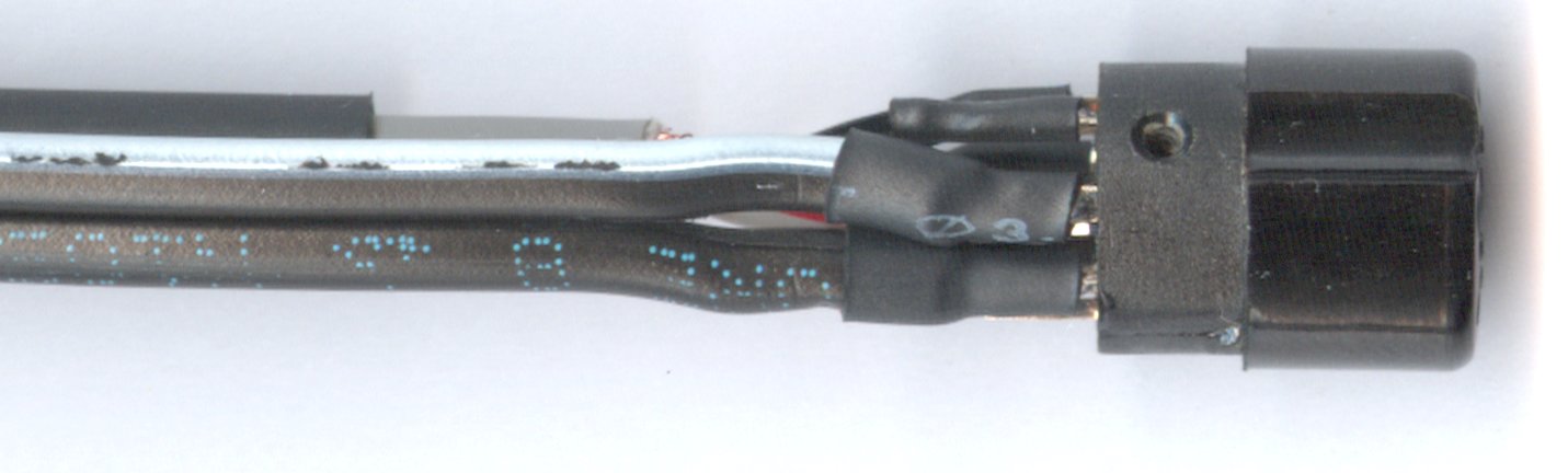
Here's a close-up of the previous step - the soldered ends of the 8 pin connector. The thin wires are shown. |
|
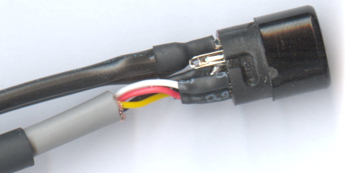
here's another close-up of the soldering, but the thick wires are shown, and the heatshrink has been pushed over them. Again, check for shorts or opens between all conductors and the shield of the grey cable. |
|
|
Here's a third shot of the end, from a different angle, and showing the unsoldered pin 5. The heatshrink has been pushed down and heated. Note that the central pin 8 (copper braid) should be the first pins to be soldered. Also note that some of the braid has been removed to make it thin enough to solder to that pin. |
|
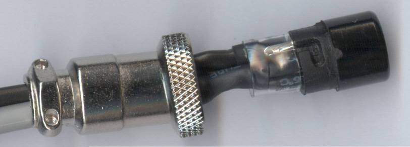
The medium sized heatshrink has been pushed over the circular connector and heated. The clear tubing (non-heatshrink) has been pushed closer too. |

|
|
This shows the final resting place for the clear tubing. the circular shell is now eased back down the cables, making sure they slide back without twisting or removing their PVC insulation. |
|
The large heatshrink tube is now pushed down into the small hole in the connector's shell. The image shows the effect after heat has been applied to the heatshrink. Note that the fibreglass braid is under the heatshrink and the housing's single screw has been re-inserted. |
|
The retaining bar can now be replaced and secured with the two screws. Make sure the heatshrink is shrunk properly so that no excess fouls the jaws of the bar. Lastly, a single cable tie is used to secure the fibreglass braid under the heatshrink.
|
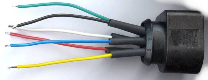
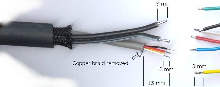
The Harness connector end of the cable attaches to the sensor. You make up the harness connector by first making up the wires that solder to the harness connector's terminals. Begin by baring 3 mm of wire at each end of the lengths of the coloured cables. |
|
|
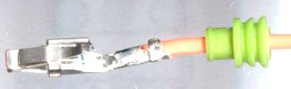
The seals are pushed on to the wires and the terminals are crimped (or simply attached with some small pliers) and then soldered carefully. Note how the wire supports are crimped after soldering (otherwise the PVC is melted). |
|
All the coloured wires can now be inserted in the correct holes - refer to the diagrams above showing the back of the harness connectors. On the 7057 connectors the purple seal retainer can be push all the way home. On the 6066 connectors the black seal retainer can be clipped into place to retain the red seals. |
|
|
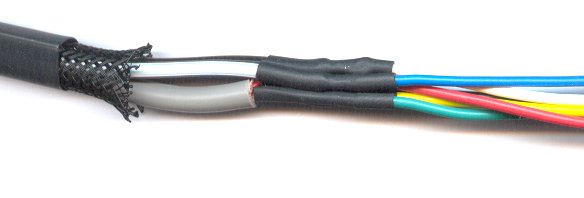
The previous image also shown the short heatshrink tubes threaded onto the harness connector end in anticipation of soldering the two ends of the cable shown in this image. Note that the 4 core wire's copper shielding braid is not attached at the harness end and is simply cut off. Click on image for important detail. |
|
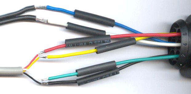
The large heatshrink tube in the previous image should not be forgotten. The small heatshrink tubes are positioned over the solder joints ready for the heat gun. Keep the large tube out of the heat at the moment - the fibreglass braid is flexible so push it away. |
|
|
The result of shrinking the small tubes - the wires have been separated for the photo, but while the heatshrink tubes are still hot they can be bundled as shown in the next step. |
|
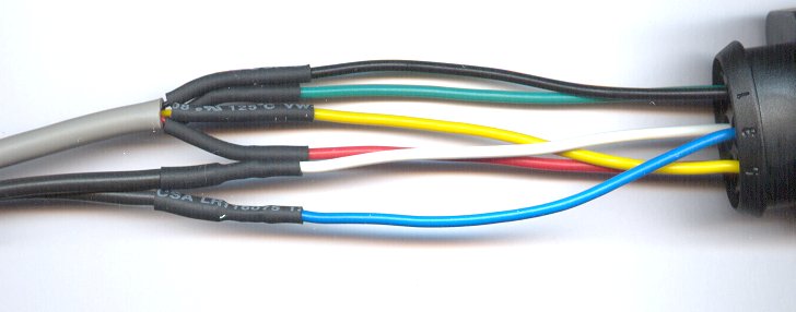
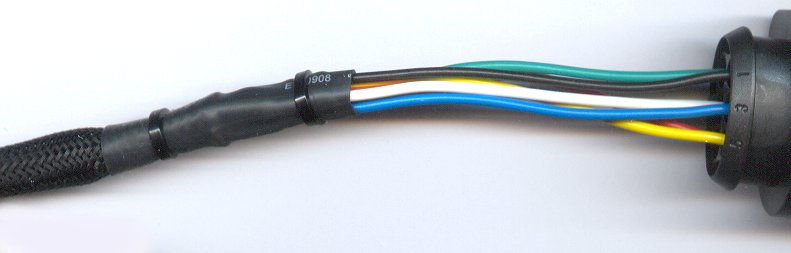
The larger heatshrink tube is moved from the left, making sure the end of the fibreglass braid is located roughly in the middle of the tube. The small bundle of heat shrunk connections should fit snugly as shown. |
|
|
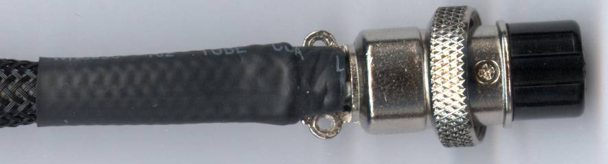
Completed harness connector end with the heatshrink pushed over the fibreglass braid and shrunk. Two cable ties have been added to secure the joints. |
Pump Cell sensors (like the LSU) should not be exposed to an exhaust stream and left unheated. The internal diffusion chamber will readily clog with carbon deposits that would be "burnt off" in normal operation.
If your wideband unit is disconnected for any length of time, you should also remove the sensor and replace the nut in the bung.
)