WBo2 3A/3E Updates, Fixes, Technical Notes, etc.

This page is designed to help explain, solve, expand, rectify deficiencies, etc.:

  • how or why things work a certain way,
  • how to do things that may not be immediately obvious,
  • further explanations or technical information,
  • how we stuffed up and how you can fix or modify things.

Model Differences 3A1, 3A2, 3E1 & 3E2

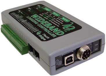
First a quick reminder of the differences between the 3A and 3E models. The 3A and 3E models share the same basic circuitry, case and label and even have the same firmware version for a given sensor type. The 3A models do NOT have an inbuilt display, the 3E models have an inbuilt 4 digit red LED display that has a subset of the capability of external displays like the LD02.

The 3x1 models do NOT have internal logging memory whereas the 3x2 models have 1 Mbyte of internal logging memory as well as a USB interface. The USB (a USB-B socket) interface replaces one of the two 8 pin RJ45 serial sockets.

The label on each model is the same but not all buttons have a function. the 3A1 has only a functional CAL button. The 3A1 adds the LOG button. The 3E1 and 3E2 add the DSP display to change the currently displayed view.

Index

At the moment we have a small list of problems. We hope to expand it with your feedback


CAL button Not Working?   Wiring Issue   [April 2009]

Problem: Some time in late 2008 we shipped a number of 3A and 3E controllers with an internal wiring fault. This disabled the CAL button.

Background: The CAL button on 3A and 3E units must be held down for around 5 seconds before it will spend around 15 to 20 seconds to try and calibrate itself with the currently attached sensor. The calibrate function must first have the sensor correctly attached and heated to operating temperature (ie. the status LED should be showing a steady GREEN). otherwise the button will be ignored.

Workaround: On some 3A1 and 3E1 models the LOG button was installed although there is no internal logging function available on these models. The logging button can be used to calibrate the controller by holding it down for at least 5 seconds. For 3A2 & 3E2 models the controller must be in the non-logging-active mode before the CAL function can be activated. The Free-air calibration section of wbUTIL can also be used to free-air calibrate the controller.

Permanent Fix: For units that do indeed have a wiring fault, the fix is to change a single wire! Refer to the images at right (click on the images for a larger pop-up) showing the back of the PCB at the button end.

In the left image the Error label and the arrow point to the incorrectly positioned wire. This wire connects one side of the button to GND, and should be removed. The upper image at right shows one solution with the Update label pointing to the added wire. Another solution is the second image which reuses the existing wire.

Thermocouple (or User 4 to User 6) Channels not working [April 2009]

Problem: The four thermocouple channels (labelled as User 4 to User 7) show a large amount of bleed-through from other channels. A incorrect value capacitor was used on some units. This problem is NOT observed when the User 4 to User 7 channels are set to be 0 to 5 Volt inputs (ie. jumper J5 in the x1 position).

Background: The thermocouple/User channels on the 3A/E model is very similar to the original 2A0 circuit. The 2A0 had three channels, and the 3A/E model adds another channel. All channels are multiplexed onto a single A/D converter channel. A single capacitor (C402 on the 2A) provides a small amount of noise reduction and filtering. Some time in the manufacturing phase this small value capacitor was increased from 100 pF to 1 nF (0.001 uF). The effect of this larger capacitor (and different timing on the 3A/E) is to store charge so that, for the x101 range, when the multiplexer changes to the next channel, a percentage of the previous channels value is added to the next channel.

Workaround: If you don't use thermocouple channels, or if you use these extra channels as 0 to 5 Volt inputs (ie. jumper J5 in the x1 position), then no workaround or fix is needed.

Permanent Fix: A simple permanent fix is to totally remove the offending capacitor. The stability of the x101 amplifier appears to be good without this capacitor, so just get rid of it! The easiest way to do this is with some sharp side cutters.

Locate the capacitor C402 (double check and check again!), then heat one side of the capacitor's mounting point. As soon as the solder melts (in about one second!), with small "electronic side cutters", snip the capacitor in half. With solder wick remove the solder from both sides of the capacitor's mounting point. It's possible to slide the other half of the snipped capacitor away from the PCB trace with the solder wick - the capacitor can then be shaken off the board.