WBo2 version 3A1, introduced in November 2006,
is Tech Edge's full featured professionalsingle-channel wideband unit.
In 2010 we started shipping in a black ABS (flameproof) case.
3A1 is a lower cost option to the single channel 3B1
(or dual channel 3H1,
but it still includes support for more sensors,
more versatile input channels and other evolutionary changes.
WBo2 version 3A2 is also available, and described in this document, 3A2 adds a 1 M byte non-volatile on-board logging memory, and an on-board USB virtual serial port for connection to modern laptops which may not have a legacy serial port, and to increase logging data transfer speeds.
Version 3E1 & 3E2 are also available, and add an inbuilt display to the 3A1 & 3A2 described here.
More information on 3E1 & 3E2 can be found here.
Tech Edge 3A/3E Features
Accuracy within 0.1 AFR (Lambda +/- 0.005).
10.5 to 19.5 Volt DC operation (up to 3 Amps).
Uses LSU 4.0/4.2 (Bosch 6066/7057 family) or NTK (L1H1/L2H2) sensor.
WBlin Configurable wideband 5 Volt output (12 bit accuracy).
SVout for LD01 display (10 bit configurable too).
NBsim narrowband (10 bit configurable too).
3 analogue 0 to 5 Volt inputs sampled at up to 40/sec.
4 thermocouple inputs (can be converted to analogue inputs).
RPM input from Tacho or ECU for logging.
PULSE input from VSS sensor or cruise control for logging.
ALARM output with configurable software triggers, for shift lights, buzzers etc.
5 volt output for powering external sensors such as MAP or TPS.
Auto-cal button, one-touch calibration (with sensor in free-air).
Free logging software (optional extra feature upgrade available).
3A2 also includes logging and USB options :
USB Full-Speed (12Mb/s) virtual serial port - designed for modern laptop computers without RS232 ports.
100% compatible with existing PC software.
On-board 1 M Byte logging memory downloads via USB and RS232 channels to PC.
The 3A and 3E units are equivalent except for the 4 digit inbuilt display of the 3E.
Both units are described below.
Buy the 3A1/2 or 3E1/2 Configured as Follows
for
&
display.
selected cable is for this sensor family
3A1/3A2 & 3E1/3E2
LSU Sensor
Cable
Display.
Total price of selected item(s) :
quantity :
...
3A/3E Inputs & Outputs
Please note that this documentation is in preliminary form.
3A1/3A2 features two 10 pin removable I/O connectors on one side of the case.
The status LEDs and function buttons are at the top of the case,
On the top of the case (with the sticker) can be found ..
Status LED - Displays information about sensor function, and indicates errors and alarm conditions.
Heater LED - indicates the amount of power the sensor heater is drawing.
Logging LED - on models with logging functionality.
LOG Button - Some displays can also control the logging function provided by this button.
A standard 1 Mbyte of logging memory is enough for tens of minutes of recording time.
DSP Button - On models fitted with an integrated display, this button changes the configurable display 'views', typically between Lambda, AFR, RPM etc.
CAL Button - When held down, initiates the Auto-cal sequence (indicated by a series of sharp flashes on the logger LED) .
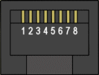
The end of the case carries the sensor cable connector, the power connector
and USB connector.
Sensor Cable Connectors - these connect to a range of sensor types,
with the recommended sensor being a low cost LSU 4.2 sensor from Bosch.
Cables for each sensor family and connector type are used to customize the unit to the sensor
Firmware and jumper settings may also need changing.
Power connector - is normally wired to the vehicle's power via a high current (5 Amp) in-line fuse and then to a switched power point.
Power is normally made available when the ignition is switched to ON.
We discourage temporary installations using a cigarette lighter because the sensors should always be powered when exposed to exhaust gasses.
USB port - the USB port works like a fast serial port and even appears to an attached PC as an additional serial port.
This feature ensures total compatibility with existing software without sacrificing speed. Units without internal logging may have a second RJ45 fitted rather than a USB port.
The side of the case carries the two 10 pin connectors, the RJ11
and RJ45 connectors.
10 pin Connectors - These are explained in detail below, and provide convenient pluggable screw terminal connections for outputs (WBlin, NBsim, etc.), as well as inputs (User 0-5v inputs, Thermocouples, RPM). .
RJ11 Connector - Intended for use with a future intelligent display.
RJ45 Connector - Provides a connection for external displays, and RS232 communications with a PC using the serial port. Units without internal logging may have a second RJ45 fitted rather than a USB port..
The 3A1 unit, without cables, weighs just over 200 grams,
and the case measures 150 x 80 mm with height of 30 mm.
The connectors at the back plus side combined protrude a further 15 mm.
Sensor, power and display cables are compatible with other 2.0 units
but the green pluggable logging connectors are assigned differently to other units.
The connectors are shown in the images below.
Leftmost 3A1 green connector, Y5.
Rightmost 3A1 green connector, Y2.
Click on each image to obtain a schematic view of the connectors
or see the brief connector summary.
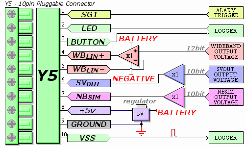
GREEN Logging Connector (Y5) Outputs (
WBlin,
NBsim,
SVout,
5 volt supply,
Logging Button &
ALARM).
SG1 - Also called 'ALARM', This is a software configurable switched ground for shift lights, alarm buzzers, etc.
EXT LED - A buffered and current limited output for driving an external logging LED.
BUTTON - A protected input that may be connected to an external logger button, connect to ground to activate.
As 3A1's major function is to measure AFR (or Lambda), the unit provides three (3)
software configurable 0 to 5 volt outputs
(WBlin, SVout & NBsim) that can be mapped to the currently sensed AFR.
As well, an RS232 data stream provides digitally precise information on sensed AFR and all logged inputs.
These outputs are described in detail in the following paragraphs.
Note: Pin 3/Y1 refers to pin 3 on the 8 pin RJ45 connector Y1.
The wideband signals
SVout[pin 1],
WBlin[pin 4] &
NBsim[pin 6]
signals are all described in detail below.
A fused, protected and partially filtered battery voltage Vbatt
is available from [pin 8].
This output is provided to power other devices such as the LA1 display or the LD02.
It should only be connected to devices that will draw small currents; typically less than 100 milliamps.
Excessive current consumption may cause heating of an internal dropping/protection resistor.
A ground GND point [pin 5] is provided as a return for the RS232 and Vbatt connections.
The RS232 signals themselves are on
Rx[pin 2] &
Tx[pin 3].
The WBVout[pin 7] represents the raw buffered Ip current
but is not that useful as it is not calibrated to any standard and is not described further.
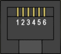
6 Pin RJ11 Connector - LSS Tx & SVout
The 6 pin RJ11 connector is designed for use with an intelligent serial display.
Its primary feature is a second serial channel called the Low Speed Serial (LSS) interface
which has a 1200 baud data rate (ie. low speed) which is adequate for most displays.
Additionally there is a duplicate of the SVout signal also found on the two RJ45 connectors, as well as a Logging Button connection, that can be brought out to an external pushbutton and used on, for instance, a dashboard. The Button signal is connected to Ground to activate it.
The RJ11 connector includes the following signals :
BUTTON[pin 1-RJ11] Connected to Ground via an external pushbutton to duplicate logging button.
LSS Tx[pin 2-RJ11] is not currently supported in firmware.
Vbatt[pin 6-RJ11] &
GND[pin 4-RJ11]
provide current limited power and a return GND for the external display.
NBsim[pin 3-RJ11] is a duplicate of the NBsim signal found on the Green Connector.
SVout[pin 5-RJ11] is a duplicate of the SVout signal found on the RJ45 Connectors.
WBlinPin 4 & 5 on Y5, (Pin 4/Y1 on RJ45) Wideband Output
The most accurate of the 3 voltage outputs is WBlin which is generated by a 12 bit DAC
using a 65 word lookup table (with linear interpolation for improved resolution).
3A1 adds the capability to program WBlin to a maximum of 8.192 Volts.
A special feature of WBlin is what we have called a differential output.
The WBlin+ output pin (left pin in the image) is the signal, and the WBlin- output pin is the ground reference output.
This arrangement is designed to reduce the amount of noise and possible voltage offset errors seen by a device connected to WBlin.
The WBlin differential output is described fully here (but note that 3A1 provides up to 8.192 Volts on WBlin).
WBlin can be re-programmed using the Config utility
to cover any part of the AFR range from Lambda = 0.6 to free-air over the 0 to 8 Volt range.
The default linear wideband output is shown in the image at right.
Note that the maximum voltage is 5.00 Volts at an AFR of 19.0
(* see note-1 below).
With the default mapping as shown, when an AFR of 19 is reached, the output clamps at 5.00 Volts - this is for
100% compatibility with previous wideband models, and to ensure 5 Volt input on logging devices are not overloaded.
For the default mapping shown, to convert WBlin to an AFR,
simply multiply the measured voltage by 2 and add 9.
The advantage of a linear output is that it's easy to write a conversion function
from the wideband voltage to AFR.
* Note-1:
Remember that WBo2 is a Lambda meter and is "calibrated" to display AFR for fuels with a stoich AFR of 14.7 (ie. "unleaded").
For other fuels that don't have a stoich value of 14.7, the x-axis (AFR) of the graph shown here should be modified.
* Note-2:
while the WBlin output is accurate, the Lambda data in the RS232 data frame is inherently more accurate
and does not suffer from some possible sources of signal degradation that beset all analogue data.
SVoutPin 7/Y5, (Pin 1/Y1 on RJ45) Compatibility Output
The SVout signal is intended for analogue displays like the LD01.
To generate SVout, the processor uses a 65 word lookup table with linear interpolation.
It converts the normalised pump current (Ipx) into a 10 bit value representing SVout.
A hardware PWM (Pulse Width Modulation) pin on the processor generates the actual SVout voltage.
SVout is compatible with the Vout signal from the original
oz-diy-wb unit (and the 1.5 unit's Vwb).
It can be used to drive the analogue LD01 display (or the older 5301 if you change its connector).
Note that the 12 bit WBlin can be re-programmed to use the SVout table,
so if you're not using WBlin and you want a more accurate SVout voltage,
you should consider reprogramming WBlin.
Remember however that SVout covers the full range of full-rich (Lambda=0.6) to free-air, the voltage range is small (less than 3 Volts)
so measuring resolution is reduced compared to using a smaller AFR range over a larger voltage range.
The default SVout, shown at right, varies between about
1.0 Volt for a very rich mixture (Lambda=0.6 or AFR=9), to 2.50 Volts
for a stoic mixture, and to 3.1 Volts for a lean mixture (AFR=25).
In free-air the SVout should be exactly 4.00 Volts when the unit has been free-air calibrated correctly.
The default AFR vs. SVout relationship is shown in the Vout table/graph page.
The analogue Vout is a continuously available signal that may be logged with a high speed logger.
We recommend at least a 10 bit converter for best accuracy.
NBsimPin 6/Y5 Simulated Narrowband Output
A synthesized narrowband (NBsim) voltage is produced by the onboard microcontroller
using a 10 bit A/D PWM converter (with single pole filter), and a 65 word lookup table. Linear interpolation improves lookup accuracy.
The full 0 to 5 Volt output is available, but restricting the output to 0 to 1 volt reduces the number of possible steps to around 200 (~5 mV per step).
The NB output is designed to be compatible with
the raw output of a Bosch LSM-11 sensor. Refer to this
eXcel spreadsheet
for the graph of the default NBsim vs AFR.
As NBsim can re-programmed it is possible to do a number of
interesting things such as fooling the engine's ECU (if equipped with a NB sensor)
into running richer or leaner than it would do otherwise.
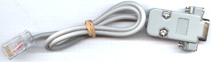
Serial RS232 RxPin 2/Y1, TxPin 3/Y1 & GNDPin 5/Y1 (on RJ45)
The 3A1's RJ45 connector (Y1, rightmost connector on the side) carries RS232 and other signals.
The unit transmits logged data on its Tx line [pin 3] and
receives commands (from PC or display) and code updates from a PC on its Rx line [pin 2].
The diagram at left shows the wires within the cable and also the connections at each end.
Note the pin names change from left to right - the WB unit's Tx pin transmits to the PC's Rx pin (and vice versa).
[pin 5] is the shield for the Rx and Tx data lines as well as being the return data path.
WBo2 to PC cable
Here's an image of the actual RS232 cable for connection between a PC and the WB unit.
The cable is used for either logging to a PC, or for re-flashing its code (under control of a PC).
If you need to extend the cable then a standard straight through male-female DB9 extension cable should be used
(ie. not a cross-over or null modem cable).
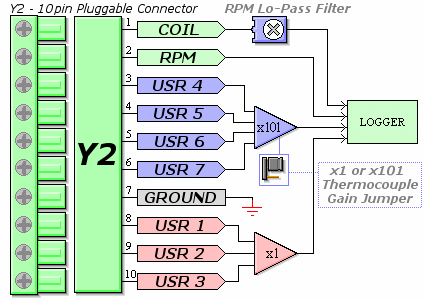
3A1 has two green 10 pin pluggable connectors (y2) on the side of the case.
The inputs are shown in the diagram at right.
The inputs, counting down from 1 at the top to 10 at the bottom are :
COIL - primary PULSE channel, A protected version of RPM LO, May be connected to a tachometer style 0-12v output.
RPM LO - Primary PULSE channel, may be connected to an ECU or ignition module 0-5v output for logging RPM.
GROUND - Ground return for single ended outputs & 5v output.
USR1 - USR3 - Single channel 0-5v Analog voltage inputs.
Note:USR4 to USR7 - Thermocouple inputs can be re-configured to 0-5v inputs.
Analogue Inputs
USER1USER2 &
USER3
The right three pins of Y2 are the three 0-5 Volts single endedanalogue inputs (USER1 through USER3).
They can be used for sampling voltages such as TPS (Throttle Position Sensor) and MAP (Manifold Absolute Pressure),
but remember that the measured voltage should not exceed 5 Volts.
They are not suitable for measuring pulse inputs unless the pulses have been processed by an external circuit.
The USER voltages are sampled at a resolution of 10 bits at a rate determined by logging configuration parameters (default 10 sample/sec).
The 3 channels have at least a 10k ohm input impedance.
The 10 bit resolution means variation as small as 5 milliVolts can be detected, but in practice
the noise limit sets the resolution to as low as 15 to 20 milliVolts.
The diagram at left shows how to connect the two possible types of inputs to the USER inputs.
The Single Ended Input positive signal wire (+) goes to one of the input pins (Pin 10 = USR 1 in this case),
and the return path for the signal is via the vehicle's wiring.
The Floating Input positive signal wire goes to another input pin (pin 8 = USR 3 in this case)
and the return path for the signal is via the GROUND pin (pin 7) rather than vehicle's wiring.
Note that unterminated inputs will float and may show a voltage level when not being used.
Either ignore this effect or physically connect all unterminated inputs to GND (pin 7) with short pieces of wire.
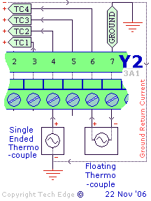
Thermocouple Inputs
TC1TC2TC3 &
TC4
Pins 3 - 6 of Y2 are four single endedthermocouple inputs.
There is a single thermocouple amplifier (with a 4 input MUX or multiplexor)
that amplifies the very low level thermocouple signals (voltage gain is 101 times).
The K type thermocouples used allow a temperature range of ambient to just over 1,200°C
(The actual voltage input is in the range 0->49.5 milliVolts).
3A1 also has an internal thermistor that is used to measure ambient temperature so that ice-point compensation
can be applied to the raw thermocouple data to give better accuracy.
There are two types of thermocouples; ones with two terminals and one with a single terminal that is used with a ground return.
Both types can be used although only the double ended (or floating) one will give noise free results in an automotive environment.
The floating thermocouple is attached between ground and the signal input (see image at right).
Some thermocouples have screw or bolt attachments and use a single wire.
These will work but they will be noisier than a two wire thermocouple.
We don't necessarily recommend these people, but http://www.exhaustgas.com
should be consulted to give you an idea of what's available.
Check their part number 4018-48-R-W (48 inch long wire, weld on bung, stinger model).
Or for their probes
look at the bottom of the page for the products
they make to suit Westach instruments. All of these probes are
manufactured with terminals which suit the green connector really well.
The image shows the (+)ve terminal insulated with heatshrink.
The tabs on the EGT probe's end wires have been "streamlined"
to prevent hitting each other during operation.
The K-type thermocouples are made in either a clamp-on style, a weld-on style,
a high quality bullet probe, or the stinger probes (2 year warranty).
Their bullet probes work on 1000 hp/cylinder top fuel cars and need to last 100 passes.
Here's a pop-up image of a hose-clamp style EGT clamp.
Thermocouples generate a voltage that depends on the difference between the "hot" junction
where two dissimilar metals are joined, and the "cold" junction.
Basic data for K-type thermocouples is available from NIST at
http://srdata.nist.gov/its90/main/its90_main_page.html.
Thermocouple inputs may be re-configured to 0-5v inputs with a jumper shunt change, as described below.
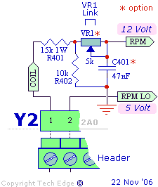
3A1 has two PULSE channels that are captured for logging.
These are separated into two inputs (RPM & VSS), with a RPM being split into two choices for input (0-12v COIL & 0-5v RPM).
Refer below for details of the Secondary VSS input.
Diagram at right shows routing of RPM input via the Low-Pass filter that can be used to assist with installations that generate a large amount of high frequency noise on the RPM pickup. :
COIL input for direct connection to a COIL (or a Tach signal as generated by some vehicles).
The pin 4 Y1 input normally connects to the wire going between the points and the COIL.
On vehicles that have electronic ignition and a distributor you would connect to
the point between the transistor switch (or ignition amplifier) and the coil.
The COIL input should never be connected to any voltage greater than 12 Volts
or damage to the WBo2 unit may result.
LO/RPM input for a lower voltage "logic level" signal as is generated by some sensors
or produced as a low voltage output by an ECU (possibly the input to a transistor ignition amplifier).
the 5 volt pulse will be at some small multiple of the engine's revs.
Unfortunately, the loading (low input impedance) of the RPM input sometimes makes it infeasible
to connect to sensitive circuits such as an inductive crank angle sensor.
The LO/RPM and COIL inputs cannot be used at the same time, ie. they are different ways of supplying a signal to the one logging channel.
RPM Noise Filtering [C401 & VR1]
3A1 includes the option of variable resistor VR1.
In practice VR1 is not that useful in filtering high frequency noise so
VR1 is not normally included on PCBs and a linkshown here
replaces VR1.
3A1 Jumper-Shunt Locations
The following sections describe how hardware options are set using on board jumper-shunts (often just called jumpers).
These shunts are :
J1 - Rescue-Reflash jumper (in the OFF position except when rescue re-flashing).
J2 - Cal Jumper - Always ON for operational state..
J3 - Sensor Select jumper, Selects between Bosch LSU sensors, and NTK L1H1 family sensors Note: Check that the correct firmware has been loaded into the 3A unit.
J4 - WBlin Ground jumper ON to connect WBlin- to Ground. see here for more information
J5 - User Input Gain selects either x1 gain to use TC1-TC4 as 0-5v inputs, or x101 gain for normal use with Thermocouples.
J6 - LSU Type Select Normal use in the 4.2 position for LSU4.2 and LSU4.0 sensors (such as our standard 7 200 sensor), Can be set to the 4.9 position for use with Bosch LSU4.9 sensors.
Click on the image or here for an enlarged popup of the jumper-shunt locations.
Rescue Jumper [J1]
As mentioned in the software section, the
reflash utility is used to update the 3A1's firmware (or operating software).
The rescue jumper is NOT normally required to be used, but may be required in the case of a rare power glitch, or failed reflash attempt.
The image at right shows the location of the rescue-reflash jumper-shunt.
There is normally NO jumper installed when the unit is not being re-flashed.
To perform a rescue-reflash take off the CAL shunt (J2) temporarily and place it on the Rescue Shunt to enable the rescue mode.
Don't forget to remove the shunt afterwards and replace in the J2 position.
Cal Jumper [J2]
During all normal operation the J2 (CAL) jumper should be installed.
It is shown here as a photo image
or as a board view.
It is located at the top of the board beside the Ground reference test point.
Sensor Select Jumper [J3]
The 3A1 has hardware support for both the NTK UEGO sensor (L1H1, L2H2 & related models)
as well as the Bosch LSU sensor (all LSU 4.0 & 4.2 models).
Go here for more information on the sensors supported by 3A1,
but remember the sensor's actual connector may be different between otherwise compatible sensors.
To change the sensor between UEGO (NTK) and LSU (Bosch), two things must be done:
Change the hardware which entails :
Changing the 3A1-to-sensor cable to match the new sensor (see cable information here).
Take off the NTK jumper J-NTK, for the NTK or leave it on for the LSU
(yes, note the reversed logic of the label.
Click on the image for a popup image of the shunt settings.
Change the firmware by re-flashing 3A1 with the latest firmware for that sensor.
Be very careful to match the J-NTK jumper shunt's position correctly as using the NTK setting with an LSU, or vice versa,
may damage the sensor or the 3A1 control unit. This warning is particularly relevant if you swap from LSU to NTK.
WBlin Ground Jumper [J4]
This shunt controls the WBlin+ output's reference input (WBlin-).
This topic is discussed here.
It is important to note that incorrectly setting this jumper can result in either:
Excessive WBlin+ noise (mostly heater switching transients at 30 Hz) on WBlin+
(with shunt installed = ON when it should be OFF and WBlin- goes to the input amp's GND).
floating WBlin+ output that can exceed 5 Volts or go below 0 Volts
(shunt is OFF when WBlin- is left floating).
Note that the effect of the J4 shunt can be reproduced by wiring WBlin- & GND together with a short piece of wire.
This obviates opening the case to access J4 (but make sure J4 is off when you need it off).
User Input Gain Jumper [J5]
This shunt switches whether the four user inputs (USR4, USR5, USR6 & USR7) are used for thermocouples or a 0-5 Volt input. Set it in the x101 position for thermocouple operation, or in the x1 position for normal 0-5 Volt inputs.
LSU Type Select Jumper [J6] - Bosch LSU 4.0/4.2 or 4.9 Support
The 3A1 supports various models of Bosch LSU sensor, Changing between Bosch LSU 4.0/4.2 or 4.9 requires a different firmware file.
Remember to change the firmware by re-flashing 3A1 with the latest firmware for that sensor.
COIL Low Pass Filter [VR1]
The COIL input may be connected to the terminal of a conventional ignition coil system. (or a Tach signal as generated by some vehicles), On vehicles that have electronic ignition and a distributor you would connect to the point between the transistor switch (or ignition amplifier) and the coil. The COIL input should never be connected to any voltage greater than 12 Volts or damage to the WBo2 unit may result.
In some situations, it may be beneficial to adjust VR1 to reduce the effect of high frequency noise coupled into the RPM pickup, VR1 acts as a Low Pass filter (or high frequency attenuator).
VR1 is usually shipped with a wire link in place, as this gives the maximum range the RPM circuit is capable of.
Operation of the LEDs (Logger, Status, Heater)
The unit has three LEDs. Their Normal operational status is described below.
From left to right the LEDs are :
RED = Logger LED indicates on-board logging status.
GREEN/RED = Status LED
Bicolour LED flashes while the sensor is warming up, to indicate error conditions, and to indicating on-board logging status. Should be solid green to indicate normal operation.
AMBER = Heater Power LED
shows the level of power being supplied to the sensor's heater.
It should flicker reasonably brightly at 30 Hz.
Diagnostics from the STATUS & AMBER LEDs
Normal Operation :
The unit should always have a steady GREEN LED.
The AMBER LED is brightly LIT but will flicker at 30 Hz (just perceptible).
The intensity of the AMBER flicker will give some idea of how much power is being used to maintain the heater's temperature.
Normal - Heating :
Just after the unit has been turned on the normal heating cycle will cause the STATUS LED
to flash RED about once a second with a short sharp ON time, and longer OFF time.
The AMBER LED will produce a small amount of flicker (30 Hz), but should be brightly LIT.
This should last 20 to 30 seconds for a cold sensor.
If the time is much over 30 seconds then either the battery voltage may be low
or the sensor is placed where it is being excessively cooled by the gas flowing past it.
A cool sensor position may result in reduced sensor life and inaccurate measurements.
Error - No Heating :
If the sensor cable is disconnected or damaged,
the battery voltage too low or too high,
or some other problem with the heater circuit occurs,
the STATUS LED will flash RED with a fast regular ON - OFF beat twice a second
While these conditions remain the AMBER LED will be mostly DIM
but will produce a very sharp flicker a few times a second
(the unit is looking for sensor or sampling battery voltage).
This condition can occur during starting or when there is excessive battery drain during idle.
It may be an indication of a poor battery or alternator/regulator, or connection to the wrong point of the vehicle's wiring.
Unlocked PID :
It's possible for transient conditions to cause the STATUS LED to flash RED briefly.
As long as the AMBER LED and green POWER LED remain on
then this is an indication of a PID unlock condition.
A PID unlock is not necessarily an error, but it does indicate either very rapid changes in heating or cooling of the sensor,
and/or rapid changes in the ambient air-fuel ratio.
If this occurs without an explanation (such as rapid changes in throttle position) then it
may be an indication of an intermittent somewhere in the wiring, or an aging sensor.
Both the LD02 and the TEWBlog logger indicate these conditions.
The heater PID sharp single RED flash is shown.
This condition indicates may indicate the sensor is positioned where it is either too hot or too cool.
A wideband PID is indicated by a sharp double RED flash as shown here.
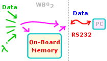
3A2 has 1 Mbyte of on-board logging memory, this is up from the 32 kbytes of 2A1.
1 Mbyte is enough memory to save about 60 minutes of data sampled at 10 times a second.
The diagram at left is an overview of how 3A2's logging works (see here for detailed technical info).
It shows 3A2 collecting data from both the Lambda sensor and the other inputs (described above).
That data can be immediately sent out the RS232 connection,
and it can also be saved in the on-board memory.
Data saving is controlled by the ON-BOARD LOGGING
button to the left of the RED LED.
Getting that data back is controlled by software commands that are issued to 3A2 from a PC (TEWBLog does this automatically).
Serial PC Logging & Software :
Direct and unlimited logging from the serial RS232 port to a PC or handheld device is performed by default.
This allows WBo2 to log and store a virtually unlimited quantity of information.
Win32 and other platform Logging software is available right now.
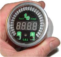
On-board logging is also controlled by the LA1 or LD02intelligent display.
These displays have a single button that turns on-board logging on or off with a single press, this provides a convenient way of activating logging (and receiving feedback on the logging status) from the dashboard of a vehicle.
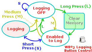
Logging Button Operation & Red LED Logging Status - 3A2/3E2 option
A combination of short, medium, and long button presses commands the on-board logger
to enter one of three states - Stopped, Enabled and Logging.
Short press is from 0.2 to 1.5 seconds.
Medium press is from 1.5 to 4 seconds.
Long press is greater than 4 seconds.
slow flash (on-off every second) = enabled for logging.
double flash (two flashes every second) = logging.
Here are the simple steps to using on-board logging - refer to the state diagram at left for the complete scheme :
a medium press puts the unit into enabled state, then ..
a short press starts or stopslogging - multiple sessions are possible.
a medium press returns to the stopped state.
a long press from the stopped state enters the enabled state ANDclears all recorded data (use before a new recording session).
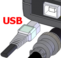
3A2/3E2, as well as including 1 Mbyte of on-board logging memory, includes a USB interface and just one single RJ45 RS232 port.
This USB interface implements an internal RS232 to USB interface to:
Maintain 100% compatibility with existing PC software - the 3A/3E unit looks just like a standard COM port to existing software.
Provide a much faster transfer rate for logged data from on-board memory (data rates for real-time logging of data remain the same).
Please note that the 3A2 and 3E2 models, although they have a USB-B connector, may not be shipped with a USB cable.
A standard USB-A to USB-B cable is available at low cost (as low as $1) from many retail outlets.
If you already have a USB device (scanner, printer, etc) then you probably already have the correct cable.
Shorter USB cables tend to be the most reliable.
Auto-Cal - Automatic Sensor Re-calibration
Auto-Cal Operation : the actual Auto-Cal process is started by pressing the CAL
button for a long press - which is at least 4 seconds.
The red logger LED will start 3 short flashes which should continue for about 15 seconds,
and then terminates with 6 short flashes.
During Auto-Cal:
Don't blow on the sensor - the carbon dioxide from your breath will affect the results.
Don't move the sensor nor change the battery voltage.
Allow about two minutes of operation before the Auto-Cal is started.
to prematurely terminate the process, press the button once - the logger LED flashing will stop.
Please read the rest of this section!
we advise you to perform an auto-cal operation when you receive your new unit and sensor.
Calibration is the process of making the unit read as accurately as possible.
3A/3E is shipped pre-calibration to a real sensor but different sensor families exist and
this requires a re-calibration with the actual sensor you have.
Bosch sensors have a neat inbuilt calibration resistor that our units work with (see image at right).
Once a sensor is calibrated, very good accuracy is maintained when another sensor of the same type is substituted.
The major reason for having a calibration function is to initially calibrate the unit to a sensor,
and then to account for any aging of the sensor (or control unit) that affects its calibration.
Calibration need not be carried out regularly (as some other manufacturers suggest).
The Auto-Cal function makes it easy to re-calibrate - almost too easy!
To explain this we need to look at how calibration works.
Basically the sensor must be placed in a known concentration of oxygen (and/or fuel) and
the "gain" of the controller adjusted to match the sensor/controller's desired output.
During calibration the sensor's environment is critical for correct results.
The sensor must be placed in free-air which means the sensor is
directly exposed to fresh, clean, normal air that anyone could breath
(ie. it is not sitting in an exhaust pipe)
We make these assumptions about free-air :
calibration occurs at close to sea-level pressure - lower pressures means lower concentrations of oxygen.
it is very close to having a free-air oxygen concentration of20.9% -
this is the basic free-air calibration assumption and this figure is surprisingly consistent around the globe.
there is negligible hydrocarbon fuel content in the air - within the sensor fuel chemically fights against the free-air oxygen content.
sensor is at an average humidity - high humidity reduces the effective oxygen percentage.
there is no carbon dioxide content in the air - like water, this lowers the free oxygen concentration
(note: don't blow on the sensor as your breath can dramatically affect the calibration).
sufficient time has passed for the sensor to reach a stable operating temperature - give it 2 minutes in free-air.
If any of these conditions are significantly different, then, although the sensor may calibrate to some value,
it will not be as accurate as possible.
The basic risk for a sensor placed in an exhaust system, and with an Auto-Cal function,
is that re-calibration could occur with the sensor in a "dirty" atmosphere.
It is vitally important that any re-calibration occurs with the sensor out of the exhaust pipe
Calibration Resistors : We are regularly asked about the calibration resistor.
The resistor is laser trimmed by Bosch as one of the last steps of the wideband sensor's manufacturing processes.
You can see this resistor in the image above - it is located behind the circular sealed section of the 6066's connector.
The black line in the enlarged part of the image is the trimmed section - the laser burns the resistor which changes its value.
Other sensors are similar - the 7057/7200's resistor is shown circled at right.
The important thing to remember is that the value of the resistor is relevant only for that sensor it was trimmed to.
It's not meaningful to measure the resistor value and then use that value for a different sensor.
Note also that, for the LSU sensor, one end of the calibration resistor is connected to
Ip (or pump current = RED wire).
The LSU calibration resistor has a guaranteed value of between 30 to 300 ohms,
but the most common values will be between 80 and 140 ohms.
Further Information
We update 3A1 documentation from time-to-time in response to your feedback (see footer below).
)
)
)


 3A1 has two green 10 pin
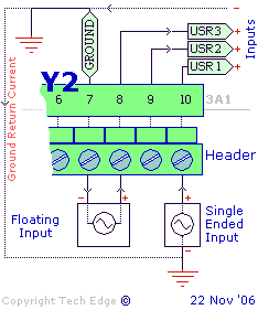
)
)
)
)

)
)
)
)

 Normal Operation :
The unit should always have a steady GREEN LED.
The AMBER LED is brightly LIT but will flicker at 30 Hz (just perceptible).
The intensity of the AMBER flicker will give some idea of how much power is being used to maintain the heater's temperature.
Normal Operation :
The unit should always have a steady GREEN LED.
The AMBER LED is brightly LIT but will flicker at 30 Hz (just perceptible).
The intensity of the AMBER flicker will give some idea of how much power is being used to maintain the heater's temperature.
 Normal - Heating :
Just after the unit has been turned on the normal heating cycle will cause the STATUS LED
to flash RED about once a second with a short sharp ON time, and longer OFF time.
The AMBER LED will produce a small amount of flicker (30 Hz), but should be brightly LIT.
This should last 20 to 30 seconds for a cold sensor.
If the time is much over 30 seconds then either the battery voltage may be low
or the sensor is placed where it is being excessively cooled by the gas flowing past it.
A cool sensor position may result in reduced sensor life and inaccurate measurements.
Normal - Heating :
Just after the unit has been turned on the normal heating cycle will cause the STATUS LED
to flash RED about once a second with a short sharp ON time, and longer OFF time.
The AMBER LED will produce a small amount of flicker (30 Hz), but should be brightly LIT.
This should last 20 to 30 seconds for a cold sensor.
If the time is much over 30 seconds then either the battery voltage may be low
or the sensor is placed where it is being excessively cooled by the gas flowing past it.
A cool sensor position may result in reduced sensor life and inaccurate measurements.
 Error - No Heating :
If the sensor cable is disconnected or damaged,
the battery voltage too low or too high,
or some other problem with the heater circuit occurs,
the STATUS LED will flash RED with a fast regular ON - OFF beat twice a second
While these conditions remain the AMBER LED will be mostly DIM
but will produce a very sharp flicker a few times a second
(the unit is looking for sensor or sampling battery voltage).
This condition can occur during starting or when there is excessive battery drain during idle.
It may be an indication of a poor battery or alternator/regulator, or connection to the wrong point of the vehicle's wiring.
Error - No Heating :
If the sensor cable is disconnected or damaged,
the battery voltage too low or too high,
or some other problem with the heater circuit occurs,
the STATUS LED will flash RED with a fast regular ON - OFF beat twice a second
While these conditions remain the AMBER LED will be mostly DIM
but will produce a very sharp flicker a few times a second
(the unit is looking for sensor or sampling battery voltage).
This condition can occur during starting or when there is excessive battery drain during idle.
It may be an indication of a poor battery or alternator/regulator, or connection to the wrong point of the vehicle's wiring.

 A wideband PID is indicated by a sharp double RED flash as shown here.
 slow flash (on-off every second) = enabled for logging.
 double flash (two flashes every second) = logging.
)
)
)
)
)
)
)
)
)