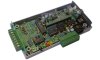
The image at left shows how a 2Y unit is connected to other WBo2 wideband components.
Please note, there are some Popup
images (JavaScript needed) on this web page.
Clockwise from top right, the
2Y's power is provided by the two pin power cable.
Then the Bosch LSU
sensor is connected via the Controller-to-Sensor cable
(available in various lengths).
(The NTK L1H1
sensor may possibly be supported in the future.)
The Controller-to-Sensor cable's
circular 8-pin
connector plugs into the 2Y unit.
On the front and end of the case are two 8-pin (RJ45)
connectors for the RS232 serial port, which is in the unit.
A Tech Edge display or an RS232 (COM) port of a PC may be
plugged in to either RS232 connector on the unit.
Then the PC may display the data from the unit.
Also the data may be logged for later display or analysis.
The 10-way green pluggable header connector is used for
configurable voltage outputs, a 5 volt 500mA supply for powering
external sensors (MAP, TPS etc.), an RPM and COIL
input, and a connection for an external logger button (labelled "Log Btn").
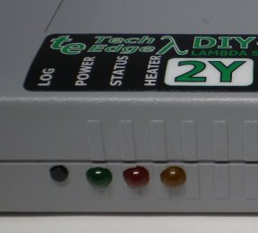
The three LEDs are for power present (GREEN),
operational status reporting (RED) and sensor
heater operation (AMBER).
The logger button is used to control on-board logging,
for units with a logger module installed.
The green endplate has an 8-way green pluggable header connector
that provides the input connections for the three user 0-5 Volt analog input
channels, as well as the three Type K thermocouple inputs.
Pin Numbers — A notation like:
Y3p4 would refer to pin 4 on connector Y3.
The 2Y unit, without cables, weighs just over 200 grams,
and the case measures 150 x 80 mm with height of 30 mm.
The connectors at the ends combined protrude a further 80 mm.
Sensor, power and display cables are compatible with other
Tech Edge Wideband units.
The connectors are shown in the images below.
Schematic View of Connectors
|
Green endplate
|
10-way green connector
|
Black endplate
|
Click on each image to obtain a schematic view of the connectors
or see the brief connector summary.
RS232 Connectors
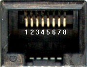

The image on the left shows the exterior appearance of an RJ45 connector for the unit's
RS232 serial port (Y1A and Y1B), complete with pin numbers.
On both connectors, the RS232 signals are on
Rx [pin 2] &
Tx [pin 3].
The unit transmits RS232 data on both Tx pins (logging frames, etc.) and
receives RS232 data (commands from PC or display, code updates from a PC, etc.)
on either Rx pin.
The ground reference (GND) for the RS232 signals is on pin 5.
There are two RS232 connectors but they are connected to the one RS232 port in the unit.
Tx is just connected to both pins 3 in parallel.
The two Rx pins go to a simple diode steering circuit which allows either Rx pin to
send data to the unit's microcontroller.
Thus, both a display and a PC can be plugged in at the same time and either device may
send commands to the unit (but not both at the exact same time).
GND also serves as the power supply return pin for
Dbatt, which is is a fused, protected and partially filtered
display battery voltage, on pin 8.
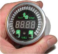
Dbatt powers connected Tech Edge displays,
such as the LX1 display,
LA1 display or the LD02.
Thus the display only needs one cable, it gets data and power from the RS232 port.
Dbatt should only be connected to devices that draw small currents;
typically less than 100 milliAmps.
Excessive current consumption will cause heating of (and possible damage to) an internal
protection resistor designed to limit short circuit current.
On both RJ45 connectors, there are also two configurable analog output voltages,
SVout [each pin 1] &
NBsim [each pin 6].
These two outputs, as well as WBlin,
are also available on the 10-way green connector.
That 10-way connector would normally be used to access all three voltages.
|
RS232 Cable
|
The diagram at left shows the wiring for the RS232 serial cable, which goes from
the unit to an attached PC.
The cable is used for logging to the PC, display of the unit's data on the PC,
re-flashing the unit's firmware (under the control of the PC), or sending a
variety of other commands to the unit.
Note that the pin names change from left to right - the unit's Tx pin transmits
to the PC's Rx pin (and vice versa).
Pin 5 is the shield for the Rx and Tx data lines as well as being
the return data path.
|
|
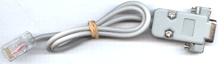
Here's a picture of an RS232 cable (at right).
If you need to extend the cable, then a standard straight through
male-female DB9 extension cable should be used
(that is, not a cross-over or null modem cable).
|
|
If you're having problems with your RS232 serial connection, please refer to the
common problems guide in the FAQ section.
Wideband Output WBlin

On the 10-way green connector is the most accurate of the three analog voltage outputs,
WBlin, which is generated by a precision 12-bit DAC
(Digital to Analog Converter) using a 65-word lookup table (with linear interpolation).
Compared to the old 2A0 unit, the 2Y's WBlin
output buffer has been
upgraded to the superior differential output.
The default linear wideband output mapping is shown in the image at right.
To convert the default WBlin voltage to an AFR simply multiply the measured voltage by 2
and add 9. The formulas are shown in the image. The advantage of a linear output
is that it's easy to write a conversion function from the wideband voltage to AFR.
WBlin can be re-programmed using the WButil configuration
utility
to cover any part of the AFR range from Lambda = 0.6 to free-air and 0 to 5 Volt output.
As well as WBlin the SVout &
NBsim outputs are available.
They use a 10-bit PWM circuit which is less accurate (WBlin is 12 bits)
and slightly noisier too.
We sometimes call these the 9.5 bit outputs to indicate their relative accuracy.
All outputs can be re-programmed using WButil's WB Tables section.
|
Configurable Output SVout

SVout (Simulated Voltage out) is an analog voltage output.
It is on the 10-way green connector (Y3p2) and the RJ45 sockets
(Y1Ap1 and Y1Bp1).
By default, it is set to suit the old Tech Edge analog
display LD01 (see image at right).
SVout is produced by the unit's microcontroller
using an internal 10-bit A/D (Analog to Digital) PWM (Pulse Width Modulation)
converter, followed by a simple low-pass filter and an op-amp buffer.
To generate the data, the microcontroller uses a 65-word lookup table with linear interpolation.
It converts the normalised pump current (Ipx) into a 10-bit value representing SVout.
We say SVout has about 9.5 bits of relative accuracy.
SVout is compatible with the Vout signal from the original
oz-diy-wb unit
(and the 1.5 unit's Vwb).
By changing the connector on the display cable, SVout will also drive the older
Tech Edge 5301 display.
Note that the 12-bit WBlin can be re-programmed
to use the SVout table,
so if you're not using WBlin and you want a more accurate SVout voltage,
you should consider reprogramming WBlin.
Remember however that the default SVout signal is non-linear, covers the full
range of very rich (Lambda=0.6)
to free air, and the voltage range is small (less than 3 Volts).
So, measuring resolution is reduced compared to using a smaller AFR range over a larger voltage range.
The default SVout table, shown at right, varies between about
1.0 Volt for a very rich mixture (Lambda=0.6 or AFR=9), to 2.50 Volts
for a stoich mixture, and on to 3.1 Volts for a lean mixture (AFR=25).
In free air, the SVout should be exactly 4.00 Volts when the unit has been free-air calibrated correctly.
The default AFR vs SVout relationship is shown in the
Vout table/graph page.
SVout is a continuously available signal that may be logged with an analog logger.
We recommend at least a 10-bit input converter for best accuracy.
|
Configurable Output NBsim

NBsim (NarrowBand simulate) is another analog voltage output.
It is also on the 10-way green connector (Y3p3) and the RJ45
sockets (Y1Ap6 and Y1Bp6).
By default, it is set to simulate the output voltage from an old narrowband sensor
(see image at right).
NBsim is produced the same way as SVout, with identical
hardware, but using a different 65-word lookup table with linear interpolation.
NBsim also has about 9.5 bits of relative accuracy.
The full 0 to 5 Volt output is available (by changing the lookup table), but
restricting the output to 0 to 1 volt (as needed for narrowband simulation)
reduces the number of possible steps to around 200 (~5 mV per step).
The NBsim output is designed to be compatible with
the raw output of a Bosch LSM-11 sensor. Refer to this
Excel spreadsheet
for the graph of the default NBsim vs AFR.
As NBsim can be re-programmed, it is possible to do a number of
interesting things, such as fooling the engine's ECU (if equipped with a narrowband sensor)
into running richer or leaner than it would do otherwise.
|
Analog Inputs
2Y wideband units have a green 8-way pluggable connector
(Y2) on the green endplate.
The inputs are shown in the diagram at right.
The inputs, counting from pin 8 at the left to pin 1 at the right are:
- USR3,2,1 - User input voltages, 0 to 5 Volt range.
- GND - Common ground (earth) return for all inputs.
- TC1,2,3 - Thermocouple inputs.
|
User Inputs
The left three pins of 8-way green connector Y2 are the
three 0-5 Volts single ended analog inputs
USR1 (Y2p6), USR2 (Y2p7) and USR3 (y2p8).
They are marked on the green endplate as V1, V2 and V3, respectively.
Remember that pin 1 is on the right of connector Y2, pin 8 is at the left.
They can be used for sampling voltages such as TPS (Throttle Position Sensor) and
MAP (Manifold Absolute Pressure),
but remember that the measured voltage should not exceed 5 Volts.
They are not suitable for measuring pulse inputs unless the pulses have been
processed by an external circuit.
The USER voltages are sampled at a resolution of 10 bits at a rate determined
by logging configuration parameters (default 10 sample/sec).
The 3 channels have at least a 10k Ohm input impedance.
The 10-bit resolution means variations as small as 5 milliVolts can be detected,
but in practice
the noise limit sets the resolution to as low as 15 to 20 milliVolts.
The diagram at left shows how to connect the two possible types of inputs to the USER inputs.
The Single Ended Input positive signal wire (+) goes
to one of the input pins (Pin 8 = USR 3 in this case),
and the return path for the signal is via the vehicle's wiring.
The Floating Input positive signal wire goes to another input pin
(pin 6 = USR1 in this case) and the return path for the signal is via the
GROUND pin (pin 5) rather than vehicle's wiring.
Note that unterminated inputs will float and may show a voltage level when not being used.
Either ignore this effect or physically connect all unterminated inputs to GND
(pin 5) with short pieces of wire.
Unused Input Pin — On the 10-way green connector, there is a
pin labelled "V4 IN".
It turns out that this pin goes to a not-connected point inside the unit,
so this pin is surplus to requirements.
|
Thermocouple Inputs
The right-most three pins of Y2 are three single ended
thermocouple inputs.
There is a single thermocouple amplifier (with a 3-input multiplexer)
that amplifies the very low level thermocouple signals (voltage gain is 101 times).
The Type K thermocouples used allow a temperature range of
ambient to just over 1,200 °C
(The actual voltage input is in the range 0->49.5 milliVolts).
The unit also has an internal thermistor that is used to measure
ambient temperature so that ice-point compensation
can be applied to the raw thermocouple data to give better accuracy.
There are two types of thermocouples; ones with two terminals and one with a
single terminal that is used with a ground return.
Both types can be used although only the double ended (or floating) one will
give noise-free results in an automotive environment.
The floating thermocouple is attached between ground and the signal input (see image at right).
Some thermocouples have screw or bolt attachments and use a single wire.
These will work but they will be noisier than a two wire thermocouple.
We don't necessarily recommend these people, but http://www.exhaustgas.com
should be consulted to give you an idea of what's available.
Check their part number 4018-48-R-W (48 inch long wire, weld
on bung, stinger model).
Or for their probes
look at the bottom of the page for the products
they make to suit Westach instruments.
All of these probes are
manufactured with terminals which suit the green connector really well.
The tabs on the EGT probe's end wires have been "streamlined"
to prevent hitting each other during operation.
The K-type thermocouples are made in either a clamp-on style, a weld-on style,
a high quality bullet probe, or the stinger probes (2 year warranty).
Their bullet probes work on 1000 hp/cylinder top fuel cars and need to last 100 passes.
Here's a pop-up image of a hose-clamp style EGT clamp.
Thermocouples generate a voltage that depends on the difference between the "hot" junction
where two dissimilar metals are joined, and the "cold" junction.
Basic data for Type K thermocouples is available from NIST at
http://srdata.nist.gov/its90/main/its90_main_page.html.
Conversion of Thermocouple Inputs to Analog
Converting all three thermocouple inputs into
analog (0 to 5 Volt) inputs can be done,
but it's not possible to have a mix of thermocouple and analog - it's all or none!
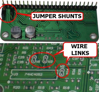
Open up your 2Y unit's case and move jumper J1 from the X101 position
to the X1 position, then reassemble the case.
See Section 12 "Jumper-Shunts" in your 2Y1 Assembly Guide for more details.
Refer to the 2Y1 DIY Wideband Kit Assembly page
for how to get your 2Y1 Assembly Guide.
Logging software will also have to be told of the change by reconfiguring it.
|
Tachometer RPM Input
A tachometer is an instrument which measures RPM (Revolutions Per Minute).
The unit has a single RPM channel that is captured for logging,
although there are two input pins provided to capture your RPM signal.
Refer to the image at right.
- COIL (on Y3p9, 10-way green connector) for direct connection to
a COIL (or a Tach signal as generated by some vehicles).
The COIL input normally connects to the wire going between the points and the COIL.
On vehicles that have electronic ignition and a distributor you would connect to
the point between the transistor switch (or ignition amplifier) and the coil.
- RPM (on Y3p8, 10-way green connector) for a lower voltage
"logic level" signal as is generated by some sensors
or produced as a low voltage output by an ECU (possibly the input to a
transistor ignition amplifier).
The 5 volt pulse will be at some small multiple of the engine's revs.
Unfortunately, the loading (low input impedance) of the RPM input
sometimes makes it infeasible to connect to sensitive circuits such
as an inductive crank angle sensor.
RPM Noise Filtering
Notice the components C31 (56 nF capacitor),
and VR1 (10k preset variable resistor).
Their physical location (bottom left of the main PCB, beside the 10-way green connector)
is shown here.
Capacitor C31 is a low-pass filter component.
C31 is supplied as a 56 nF capacitor (or 0.056 uF) and is marked as 563,
and is usually a large green capacitor.
On some vehicles (when using the COIL input) C31 may limit the maximum RPM that can be logged.
C31 can be removed entirely or replaced with a smaller value.
|
Sensor Type
|
The 2Y unit has hardware support for both the Bosch LSU sensors
(all LSU 4.0, 4.2 & 4.9 types) as well as the
NTK UEGO sensor (L1H1, L2H2 & related models).
Note carefully, hardware support is one thing, there must also be suitable firmware.
There is presently (2011) no 2Y firmware available for NTK sensors, so they cannot be used.
Go here for more information on sensors in general.
The sensor type is set using jumpers
(sometimes called jumper-shunts) on the lambda module.
The jumpers are on the underneath of the module.
They are marked with white lettering on the top of the module.
These jumpers are:
- NTK/LSU - Jumper LSU for Bosch LSU 4.0/4.2/4.9 sensors.
Jumper NTK for NTK UEGO sensors.
Note: Check for the correct firmware support, for the sensor type you are selecting.
- Vs Bias - Normally in the OFF position (NTK and LSU 4.0/4.2).
Change to ON when using an LSU 4.9 sensor.
Note: Check for LSU 4.9 firmware support.
Click on the image or here
for an enlarged popup of the jumper locations.
|
Changing The Sensor Type
Before changing the sensor type, always verify that there is suitable firmware
available to suit both the unit and the proposed sensor.
Go here for more information on what
firmware is available for which wideband unit and sensor combination.
To change the sensor type, three things must be done:
- Change the jumper settings:
Remove the cover from your 2Y unit, remove the lambda module.
Put the NTK/LSU jumper and the Vs Bias jumper in the correct positions.
Click on the image at right for a popup image of the jumper settings.
Reassemble your 2Y unit.
Label your unit with the sensor type it is now set for.
- Get hold of the latest firmware for that sensor type from
here on the WBo2 website.
Make sure the sensor is not plugged in.
Plug your unit into your PC's RS232 port, using the RS232 cable.
(Go here if you do not presently have an RS232 port on your PC.)
Find a suitable 12 Volt DC power supply, capable of delivering 3 Amps without
excessive voltage droop.
A fully charged car battery or an old computer power supply would do.
Car battery chargers are generally unsuitable because they have no
regulation and an unfiltered output, delivering current in the form of pulses,
not the nice steady supply needed for the unit.
Plug your unit into the power supply (using the unit's power cable, be
careful with polarity), power it up.
Start WButil.
(Go here if you do not have WButil loaded.)
Change the firmware in the unit by re-flashing it.
Verify that you have the correct firmware loaded in the unit by checking the version number.
That can be done by clicking the Terminal tab in WButil, then power the unit
off, click CLS, then power the unit on.
The unit will report its model nuimber and revision number.
Then logging frames will begin. Power off.
- Change the Controller-to-Sensor cable to match the new sensor.
The sensor's connector is different between different sensor types,
but stays the same for different sensor model numbers within the same type.
See more cable information here.
Once you have successfully changed the sensor type, plug the new sensor into the unit,
using the correct Controller-to-Sensor cable.
Plug in your display, if you have one.
Keep your PC plugged in and WButil running.
Conduct a basic sensor and controller test.
If that test passes, you are done, your changed unit and sensor are ready for use.

Be very careful to set the NTK/LSU jumper's position correctly, since using
the NTK setting with an LSU sensor, or vice versa,
may damage the sensor or the 2Y unit.
This warning is particularly relevant if you swap from LSU to NTK.
|
Jumper Functions
|
The Vs Bias jumper applies a small current bias to the Vs pin (from the sensor)
via a 150 kOhm resistor.
When it is ON, the unit can correctly drive Bosch LSU 4.9
(models 17025 and 17123) sensors, provided the firmware is also correct.
It is OFF for all other sensor types.
The NTK/LSU jumper alters the impedance between the microcontroller pin VsDRIVE
and the sensor's Vs pin. NTK and LSU sensors use different techniques to
control their internal temperature. The LSU sensor needs the lower impedance.
|
LEDs

The unit has three LEDs (Light Emitting Diodes).
Their Normal operational status is described below.
From left to right the LEDs are:
- GREEN = Power LED
indicates power is connected. It should never be flashing.
- RED = Status LED
flashes while the sensor is warming up, to indicate error conditions,
and to indicate on-board logging status.
The status LED is driven by a pin on the microcontroller.
- AMBER = Heater Power LED
shows the level of power being supplied to the sensor's heater.
The heater LED is simply connected in parallel with the sensor heater element,
so it is a good guide to what is happening with the sensor heater.
It should flicker reasonably brightly at 30 Hz.
Diagnostics from the RED & AMBER LEDs
 Normal Operation :
The unit should always have a steady RED LED showing (unless
on-board logging is active - see below).
The AMBER LED is brightly LIT but will flicker
at 30 Hz (just perceptible).
The intensity of the AMBER flicker will give some idea
of how much power is being used to maintain the heater's temperature.
Normal Operation :
The unit should always have a steady RED LED showing (unless
on-board logging is active - see below).
The AMBER LED is brightly LIT but will flicker
at 30 Hz (just perceptible).
The intensity of the AMBER flicker will give some idea
of how much power is being used to maintain the heater's temperature.
Please note: Unfortunately, a 2Y unit running firmware Rev 8062 will
incorrectly turn off its status LED during normal operation.
This has now been fixed! Please make sure you know your sensor type,
then go here to get the latest firmware,
then re-flash your 2Y unit and enjoy correct Status LED operation.
 Normal - Heating :
Just after the unit has been turned on the normal heating cycle will
cause the RED LED to flash about once a second
with a short sharp ON time, and longer OFF time.
The AMBER LED will produce a small amount of flicker (30 Hz),
but should be brightly lit.
This should last 20 to 30 seconds for a cold sensor.
If the time is much over 30 seconds then either the battery voltage may be low
or the sensor is placed where it is being excessively cooled by the gas flowing past it.
A cool sensor position may result in reduced sensor life and inaccurate measurements.
Normal - Heating :
Just after the unit has been turned on the normal heating cycle will
cause the RED LED to flash about once a second
with a short sharp ON time, and longer OFF time.
The AMBER LED will produce a small amount of flicker (30 Hz),
but should be brightly lit.
This should last 20 to 30 seconds for a cold sensor.
If the time is much over 30 seconds then either the battery voltage may be low
or the sensor is placed where it is being excessively cooled by the gas flowing past it.
A cool sensor position may result in reduced sensor life and inaccurate measurements.
 Error - No Heating :
If the sensor cable is disconnected or damaged,
the battery voltage too low or too high,
or some other problem with the heater circuit occurs,
the Status LED will flash with a fast
regular ON - OFF beat twice a second
While these conditions remain, the Heater LED will be
mostly dim but will flicker at a rate of about ten times a second
(the unit is looking for a sensor or sampling battery voltage).
This condition can occur during starting or when there is excessive
battery drain during idle.
It may be an indication of a poor battery or alternator/regulator,
or connection to the wrong point of the vehicle's wiring.
Error - No Heating :
If the sensor cable is disconnected or damaged,
the battery voltage too low or too high,
or some other problem with the heater circuit occurs,
the Status LED will flash with a fast
regular ON - OFF beat twice a second
While these conditions remain, the Heater LED will be
mostly dim but will flicker at a rate of about ten times a second
(the unit is looking for a sensor or sampling battery voltage).
This condition can occur during starting or when there is excessive
battery drain during idle.
It may be an indication of a poor battery or alternator/regulator,
or connection to the wrong point of the vehicle's wiring.

Unlocked Heater PID :
The Heater PID is a Proportional Integral Differential controller inside
the unit firmware, which controls the sensor temperature.
When the Heater PID is unlocked (lost control), a sharp
single OFF flash is shown.
This condition may indicate that the sensor is positioned where it is
either too hot or too cool.
(Prior to firmware Rev-48 this
single OFF flash was also used to indicate a Wideband PID unlock too.)
It's possible for transient conditions to cause the
Status LED to flash off briefly.
As long as the Heater LED and Power LED remain on,
then this is an indication of a Heater PID unlock condition.
A Heater PID unlock is not necessarily an error, but it does
indicate either very rapid changes in heating or cooling of the sensor,
and/or rapid changes in the ambient air-fuel ratio.
If this occurs without an explanation (such as rapid changes in
throttle position) then it may be an indication of an intermittent
somewhere in the wiring, or an ageing sensor.
Both Tech Edge displays and the
TEWBlog/WinLog
logger software indicate this condition.
 Unlocked Wideband PID is now indicated by a sharp
double OFF flash as shown here.
The Wideband PID is another PID controller which controls the Nernst cell
voltage Vs by varying the pump current Ip.
Both PIDs must be locked for accurate sensor measurements.
If you have earlier firmware and need to differentiate between the two conditions,
then download the latest HXF flash files and
re-flash your firmware.
Unlocked Wideband PID is now indicated by a sharp
double OFF flash as shown here.
The Wideband PID is another PID controller which controls the Nernst cell
voltage Vs by varying the pump current Ip.
Both PIDs must be locked for accurate sensor measurements.
If you have earlier firmware and need to differentiate between the two conditions,
then download the latest HXF flash files and
re-flash your firmware.
|
Logging
The normal power-up mode of 2Y series units is sending
logging frames out through the RS232 port (as a serial
data stream), to be displayed or logged to a PC or other RS232 device.
Units with a logger module installed (model 2Y1M) can
store logging data on-board, for later retrieval by a PC.
The unit can be commanded to save data in on-board mode by operating the
logger button shown at left.
All inputs, analog, thermocouple and
RPM, as well as lambda/AFR are logged.
When logging is enabled, the Status LED serves double duty, by
indicating the current logging mode .
 On-Board Logging :
The logger module memory is a 1M byte non-volatile flash memory
that can store over 37000 frames of 28 bytes each.
At a logging rate of 10 frames/sec (the default) that's over an hour.
The Logging rate can be varied up to around 50 frames/sec (12 minutes of logging)
or down to less than a frame every 2 seconds (about 5 hours).
Logging software can retrieve logged data and
send it out the unit's RS232 port (at 19,200 bit/s).
It would take over 8 minutes to download the maximum
data that could be stored.
On-Board Logging :
The logger module memory is a 1M byte non-volatile flash memory
that can store over 37000 frames of 28 bytes each.
At a logging rate of 10 frames/sec (the default) that's over an hour.
The Logging rate can be varied up to around 50 frames/sec (12 minutes of logging)
or down to less than a frame every 2 seconds (about 5 hours).
Logging software can retrieve logged data and
send it out the unit's RS232 port (at 19,200 bit/s).
It would take over 8 minutes to download the maximum
data that could be stored.
PC Logging Software :
Direct and unlimited logging from the RS232 port to the PC is performed by default.
This allows the PC to store a virtually unlimited quantity of logging information.
Win32 and other platform Logging software is available right now.
On-board logging can also be controlled by all recent Tech Edge displays.
These displays have a button that turns on-board logging on or off with a single press.
The display shows you logging status by showing "L on" or "LoFF" as appropriate,
for about a second or so.
This is a good deal more convenient than using the logger button on the unit
|
Logger Button Operation
A combination of short, medium, and long button presses commands the on-board logger
to enter one of three states - Stopped, Enabled and Logging.
The red Status LED shows you the current logging status.
- Short press is from 0.2 to 1.5 seconds.
- Medium press is from 1.5 to 4 seconds.
- Long press is greater than 4 seconds.
|
|

slow flash (on-off every 2 seconds) = enabled for logging.

double flash (two flashes every second) = logging.
|
|
Here are the simple steps to using on-board logging - refer to the state diagram at left for the complete scheme :
- a medium press puts the unit into enabled state, then ..
- a short press starts or stops logging - multiple sessions are possible.
- a medium press returns to the stopped state.
- a long press from the stopped state enters the enabled state AND
clears all recorded data (use before a new recording session).
|
External Logger Button
The Log Btn terminal of the 10-way green connector
may be wired to an external logger button, with the other terminal of the
pushbutton connected back to the GND terminal.
Please see the schematic at the right.
Inside the unit, the external logger button is simply wired in parallel
with the normal logger button, so both are used in the same manner.
The unit contains a pull-up resistor to keep the Log Btn terminal
at 5 Volts while the button is not closed.
The resistor only supplies a very small amount of current.
The unit may be damaged by high voltages applied to the Log Btn terminal,
It should only be left floating, or grounded to activate logging.
Be careful never to connect this terminal to 12 Volts.
A normally-open momentary pushbutton should be used.
A large red panel mount version is shown here, suitable for the
instrument panel of a drag car, but any ordinary pushbutton should work.
|
|
 This is the user manual for the 2Y DIY wideband controller series.
It contains technical details of the 2Y1 and 2Y1M units.
For a "newbie introduction" to what 2Y series controllers are all about,
including basic details of how it may be used,
see the introduction section of the FAQs.
This is the user manual for the 2Y DIY wideband controller series.
It contains technical details of the 2Y1 and 2Y1M units.
For a "newbie introduction" to what 2Y series controllers are all about,
including basic details of how it may be used,
see the introduction section of the FAQs.
)
)
)

)
)
)
)
)
)
)
)
)
)
)
)
)