 WBo2 version 2J2, introduced in July 2010,
is Tech Edge's economy, single-channel, entry level wideband controller.
It is priced to compete with similar models from other vendors.
2J2 is based on our 2J1 first introduced in January 2007.
WBo2 version 2J2, introduced in July 2010,
is Tech Edge's economy, single-channel, entry level wideband controller.
It is priced to compete with similar models from other vendors.
2J2 is based on our 2J1 first introduced in January 2007.
 In late 2010 we introduced the 2J9 controller
which is the 2J2 with the correct flash (HXF) file, different controller-to-sensor cable, and internal jumper set to use the LSU-4.9 sensor.
From here on, when we a describing common features of the 2J2 and 2J9 controllers, we will refer to the controller as the 2J2/9.
In late 2010 we introduced the 2J9 controller
which is the 2J2 with the correct flash (HXF) file, different controller-to-sensor cable, and internal jumper set to use the LSU-4.9 sensor.
From here on, when we a describing common features of the 2J2 and 2J9 controllers, we will refer to the controller as the 2J2/9.
 In February 2011 we introduced the 2JP diecast case professional model.
This is described on its own page because the pin-outs are quite different and it has additional cable length options
but internally it is a 2J2/9.
In February 2011 we introduced the 2JP diecast case professional model.
This is described on its own page because the pin-outs are quite different and it has additional cable length options
but internally it is a 2J2/9.
2J2/9/P is lower cost because it has slightly simpler (and lower cost) circuitry.
 Our 2C0B is a more accurate (12 bit hardware DAC output), faster response,
but more expensive wideband controller. 2C0B also includes two analog as well as RPM and VSS inputs.
Our 3A, 3B and
3E models have more inputs again,
and some of these models have internal logging memory.
Our 2C0B is a more accurate (12 bit hardware DAC output), faster response,
but more expensive wideband controller. 2C0B also includes two analog as well as RPM and VSS inputs.
Our 3A, 3B and
3E models have more inputs again,
and some of these models have internal logging memory.
Tech Edge 2J2/9 WBo2 Features
|
Here's what you get when you order 2J2 or 2J9. Note that the Bosch sensor can be added or purchased separately. A Tech Edge display is an optional item (see below to purchase).
Cables: 2J2 uses a 1.5 m cable from sensor to the sensor-connector. The 7200 sensor, that we also sell, comes with a 0.5 m. The total distance from 7200 sensor to 2J2 is 2.0 m which is adequate for most installations. The 2J9 comes with a 1.7 m cable and mates with the 17023 sensor with a 0.3 m cable. So, the 2J2 + 7200 and 2J9 + 17023 both have a controller to sensor spacing of 2.0 m.
The supplied power cable has a length of 2.0 m. The supplied RS232 cable has a length of 2.0 as well. Our displays typically have 1.8 m cables so the display can typically be placed 3.8 m (over 12'6") from the oxygen sensor.

We do NOT sell a 2J2/9 with a longer or shorter cable (ie. one size fits all!).
But, we can customise 2J2/9 for purchase quantities of 25+ (lead times apply).
Note:(*) The older, and relatively expensive, 6066 sensor will work with the 2J2
(Auto-cal range allows this for all 6066 sensors we have tested)
but the connector end must be replaced - we do not do this for individual orders,
but it can be arranged for larger orders (25+). We don't recommend, nor support, this modification as the 6066 is a legacy (being phased out) part!
The 2J2/9 is the only Tech Edge controller that must be free-air calibrated whenever the sensor is changed. This is made easy by the Auto-cal button but the sensor must be in free-air when this operation is performed. More information about Auto-cal can be found in the user's manual below.
WARRANTY: The 2J2/9 is designed and manufactured in Australia and is designed to be repairable. It comes with a 12 month "return to base" warranty from Tech Edge. The Bosch sensors we sell come with a Bosch supplied warranty.
Note : Cables include 2J to wideband-sensor cable and RS232 PC cable for logging and reflashing.
|
|
Total price of selected item(s) : quantity : ...
2J2/9 has only an RS232 port, newer laptops may have only have a USB port. This adds an RS232 port!
LSU 4.9 sensor 17123 (Bosch part #0-258-017-123) and the longer leaded 17025 (#0-258-017-025). These LSU-4.9 sensors are the newest and best Bosch makes.
LSU 4.2 sensor 7200 (Bosch part #0-258-007-200) is an update of the 7057 (#0-258-007-057).
Connection OverviewAt right is an overview of how the 2J2/9 may be connected. Button & Status LED
Detailed information on these functions can be found below. On the face of the case (with the sticker) can be found : |
) The Power Cable is our standard 2.0 m part with a 2 pin Molex connector to connect to the 2J unit.
Note that the white striped black wire is the NEGATIVE (or GND) wire.
The positive is also indicated with a piece of red heatshrink at the end of the cable.
The Power Cable is our standard 2.0 m part with a 2 pin Molex connector to connect to the 2J unit.
Note that the white striped black wire is the NEGATIVE (or GND) wire.
The positive is also indicated with a piece of red heatshrink at the end of the cable.
We do NOT supply a cigarette lighter plug because we prefer you organise a proper connection, possibly with an in-line a 5 Amp fuse. The cable should be trimmed to a minimum length and connected to at least 10.5 Volts (below this the controller will turn OFF to protect the sensor and the vehicle's battery). The sensor should be powered up with the motor - preheating is not necessary. Be aware that a badly positioned sensor can be damaged during the vehicle warm-up stage when condensation can occur within the sensor body - this is not an issue if the sensor is properly positioned.
You should NOT leave the sensor in an exhaust stream with the sensor un-powered because it will become clogged with carbon that is normally burnt off before it can accumulate.
)
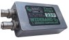
2J2/9 differs from other Tech Edge wideband units in having a controller-to-sensor cable with a low cost Molex™6-pin connector to attach to the controller (other units use a metal circular 8 pin part). The distance from the sensor to the controller, using normal cables, is 2.0 m which means the controller can be installed in the cabin of most vehicles. Also, as the connectors make it difficult to seal the case, the 2J2/9 is obviously not waterproof.
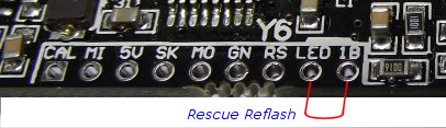
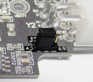
The correct controller-to-sensor cable should be used (either for LSU 4.2 or LSU 4.9), but note that if the cable and sensor type are changed, then the controller must be re-flashed and the hardware jumper J2 set to the correct position. Further information about the meaning of the wideband signals can be found on the LSU wiring page.
The red status LED indicates various problems related to the power and sensor cables, including low battery voltage and some damage (that can be detected) to sensor or the sensor-cable. In normal operation, after the heating cycle, the red LED should remain on without any flashing.
)
The green I/O connector carries most non-digital input and output signals for interfacing the controller to the outside world. No connections here are required for operation of the controller - they are all optional. The green plug is actually a two part header - the header with the screw terminals can be unplugged from the controller end. Each signal is described below using the notation NAME (N) where the number N is the pin number on the green connector.
WBlin or WideBand linear programmable output voltage is the most commonly used output. WBlin is produced by a 10 bit PWM converter (with single pole filter) that gives an effective resolution of 9.5 bits. (other Tech Edge controllers use a more accurate 12 bit hardware DAC for better performance, and this one of the major differences between 2J and other Tech Edge controllers).
A special feature of WBlin is what we call a differential output. The WBlin+ (8) output is the signal, and WBlin- (7) is the ground reference. WBlin- is actually an input and you will notice in the picture above that a small wire link is connected between WBlin- (7) and GND (6). This wire link provides a reference voltage (GND = 0 Volts) for WBlin- and in normal operation the link is removed and WBlin- is connected to the ground (GND) point of the equipment that WBlin+ is connected to.
WBlin+/- is covered in more details below or see the detailed technical information here.
NBsim (5) is another programmable output voltage that, by default, is set up to simulate the output from a narrowband sensor. NBsim on the 2J is implemented as an 8 bit PWM ADC with a notional accuracy of 7.5 bits. NBsim is covered in more details below. Both WBlin and NBsim can be re-programmed and testedusing the Output Tables tab of the WButil utility.
The RPM and Pulse inputs are used to measure the frequency of repetitive pulses. These are simple inputs that in some cases may require external components to measure some RPM signals. Most TTL level Tacho signals (often produced by an ECU) will work, but older style COIL and plug ignition systems may require a signal conditioning circuit for best operation. These inputs is covered in more details below.
User 1 and User 2 Inputs allow the controller to measure a voltage in the range of zero to 5 Volts. This is the voltage that many automotive and industrial analogue sensors produce. Devices that produce larger voltages, or have passive resistive elements, can also be used with simple external parts. These inputs are covered in more details below.
)
Two RJ45 connectors (or ports) are provided at one end of the case. Both carry the following group of signals:
RS232 serial data signals - Rx (2), Tx (3), & GND (5). These signal names are relative to the wideband unit, and Tx is an output that would normally be connected to the Rx line of a PC or display. More info on RS232 below.
Power signals (intended for a display) - these include VBATT (8) and GND (5). Only a small current (< 100 mA) should be drawn from this output as the 3.3 Ω current limiting resistor will overheat and go open circuit.
Other signals include - a duplicate of the NBsim (1) signal, and some spare (6) & (7) pins.
The WButil utility is used to configure both controllers as well as displays. Most wideband installations will use one RS232 port for connection to a display, and the other to a PC for logging. It is vitally important that any display is disconnected whenever the controller configuration is modified. Similarly, display configuration is performed using a special display adaptor (supplied with each display) and NOT while connected to the 2J unit.

2J's WBlin can output a maximum of 5.00 Volts. WBlin is a voltage representation of the Lambda (or AFR) value of the fuel being measured by the controller/sensor. WBlin can be re-programmed using the WButil utility to cover from Lambda = 0.6 to free-air over the 0 to 5 Volt range. The default programming of 2J is to cover from AFR = 9.0 to 19.0 for unleaded fuel.
It is worth remembering that 2J (like all other wideband controllers) is basically a Lambda meter. It measures lambda NOT AFR. However, a display connected to 2J can show the AFR value of the fuel.
There is a simple relationship between AFR and Lambda that depends on the stoich AFR value of the fuel. The stoich AFR value for unleaded fuel is 14.7 and this means that when the controller measures lambda of 1.0 then it's also measuring an AFR of 14.7. Other fuels (say E10) will have different stoich AFR values (E10 = 14.0 to 14.1). The stoich AFR value is important for injector (or jet) sizing but once this is handled it's often better to work in lambda units (or to think of the fuel as having a stoich AFR of 14.7, even though you know it doesn't).
For the default AFR to voltage mapping shown, to convert WBlin to an AFR, simply multiply the measured voltage by 2 and add 9. The advantage of a linear output is that it's easy to write a conversion function from the wideband voltage to AFR.
WBlin (on pin 8 and 7 of the green connector) is a differential output with the output voltage on WBlin+ (8) and a compensating input voltage on WBlin- (7). This WBlin+/WBlin- output/input scheme is used to avoid offset voltages that can occur with a single ended output. WBlin+ (green pin 8) is produced by the onboard microcontroller, using a 65 word lookup table, a 10 bit A/D PWM converter and a single pole filter. This results in effective resolution of about 9.5 bits. Other Tech Edge controllers use a 12 bit hardware DAC (Digital to Analog Converter) for better accuracy and faster performance. The DAC is one of the major differences between 2J and other Tech Edge controllers.
You must connect WBlin+ and WBlin- : The diagram at right shows how to connect the WBlin+/WBlin- output/input to another device (such as an analog data-logger or an ECU). Note how there are two wires used to connect the devices (and the 7-8 link shipped with the unit is removed). As well, note that the two devices are connected with a common ground (GND). In this diagram the two devices are also both powered from the same battery, but this is not mandatory, but remember it is mandatory that they share a common ground point for their power.
Relying on just WBlin+ and the common ground, or leaving WBlin- unconnected will result in strange values. Also, if you leave in the 7-8 link shipped with the green connector then you negate much of the accuracy that accrues with the correct connection.
* Note: while the WBlin voltage, when used correctly is quite accurate, the Lambda data in the RS232 data frame is inherently more accurate and does not suffer from some possible sources of signal degradation that beset all analogue data.

NBsim (pin 5) is a general Lambda/AFR output that is pre-programmed to appear like a narrowband voltage. NBsim is created in much the same way as WBlin (65 word lookup table) but by using an 8 bit PWM ADC with a single pole filter. A major difference is that the NBsim output is single ended, meaning that the output voltage is referenced to GND, so there is no NBsim- input to account for offset voltages. This is not a problem for the intended purpose of simulating a narrowband signal. but could be if the output is re-programmed for a different purpose.
The default NBsim output is designed to be roughly compatible with the raw voltage output of a Bosch LSM-11 sensor. Refer to this eXcel spreadsheet for the graph of the default NBsim vs AFR.
As NBsim can be re-programmed it is possible to do a number of interesting things such as:
Note that NBsim is also available on pin 1 of each RJ45 connectors - measure between NBsim (pin 1) and the GND (pin 5).
Note that a narrowband LSM-11 oxygen sensor's output is highly non-linear around a very small lambda range and at either side of this point the actual voltage levels are very temperature dependant. As there are only 65 evenly spaced data points for the NBsim to emulate the LSM-11, the NBsim signal should not be used to drive a low cost display designed for a direct connection to a "normal" narrowband sensor - it will "work" but the values displayed will often be quite different to the real wideband values.
Pulse/Repetition Inputs - RPM (4) & Pulse/VSS (3)
2J has two separate pulse or repetition channels that could be used to measure RPM and/or vehicle speed. Both inputs have simple level conditioning to avoid false readings due to signal noise. Although they can often be connected directly to signal sources they may need external conditioning (either amplification of voltage limiting) for specific applications. Tech Edge displays are set up to show RPM collected by 2J on the third view. RPM - has input conditioning (see circuit at right) designed to connect directly to older engines that use conventional coil & distributor system. The RPM line can normally be connected to the junction of the coil and the points. Many modern vehicles generate a TACHO signal and this may also be compatible with the RPM input on 2J. Alternatively, many non-ECU systems use a transistor amplifier to drive the coil and in this case the driving signal may be of sufficient voltage to be used. The RPM input should never be connected to any voltage greater than 12 Volts or damage to the WBo2 unit may result. The RPM value is sent from the 2J as a 16 bit count of 5 μSec time intervals between successive ignition events (actually it's half of the time between two successive ignition events to account for odd fire V or L engines). As the number of ignition events depends on the number of cylinders a Tech Edge display may have to be configured for it to correctly display RPM (display defaults are for a 4 cylinder 4-stroke). 
The RPM and VSS inputs can both be used at the same time, and are each is represented by a separate field in the RS232 data frame.
A quick example calculation can be used to show how VSS can be used to measure speed.
Let's assume we have a 185/60-14 tyre. This tyre size calculator
tells me that the circumference is 1,815 mm.
Let's assume we're doing 120 km/h - that's 120/60 = 2 km/min or 2000/60 = 33.3 m/sec (or 33,333 mm/sec) -
and the tyre will be revolving at 33,333/1,815 = 18.4 revs/sec or 54,451 μSec/rev, or 544 complete periods of 100 μSec.
So, if we have a wheel sensor that produces a single pulse per rev, we'll have a count value of 544 that corresponds to 120 km/hour.
|
RS232 - Link to PC and/or Display
The two black RJ45 connectors on the 2J unit may be used to connect a display and/or a PC to the 2J. Refer to the wiring diagram at the right which is divided into three sections.
The additional 12 Volt pin (called VBatt) on the RJ45 connector is used to power a display or another device. The current drawn should be less than 100 mA as excessive current consumption may cause heating of an internal dropping/protection resistor. 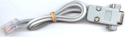
The ground point (pin 5) is provided as a return for the RS232 signals and for Vbatt. The RS232 signals themselves are on Rx (2) & Tx (3) and of course the GROUND (5) return . The signal names are relative to the controller. For connection to a PC the Tx (output) line becomes the PC's Rx (input) line. The picture is of (and older style) serial cable - newer cables have a moulded end. Note also that the NBsim signal is also available on the RJ45 connectors. |
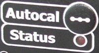
The unit has one RED Status LED that flashes while the sensor is warming up, and to indicate error conditions. Should be solid RED to indicate normal operation.
Unlocked PID : It's possible for transient conditions to cause the STATUS LED to flash OFF briefly, this is an indication of a PID unlock condition. A PID unlock is not necessarily an error, but it does indicate either very rapid changes in heating or cooling of the sensor, and/or rapid changes in the ambient air-fuel ratio. If this occurs without an explanation (such as rapid changes in throttle position) then it may be an indication of an intermittent somewhere in the wiring, or an ageing sensor. Both the LD02 and the TEWBlog logger indicate these conditions. The heater PID sharp single OFF flash is shown. This condition may indicate the sensor is positioned where it is either too hot or too cool. We have information on sensor placement. Remember wideband sensors cannot cool them self, only heat!
Auto-Cal - Semi-Automatic Sensor Re-calibration)
Calibration is the process of making the unit read as accurately as possible. Another economy measure we used with 2J is to use a simpler hardware scheme that mandates a recalibration each time a sensor (even of the same type) is changed. Calibration is required because 2J is manufactured un-calibrated and does not use the sensor's calibration part (see the image at right). This also means 2J can work with a number of different sensor types. The major use of the calibration function is to initially calibrate the unit to a sensor, and then to account for any ageing of the sensor (and possibly ageing of the 2J control unit) that affects its calibration. The Auto-Cal function makes it easy to re-calibrate a sensor. In fact it almost makes it too easy! To explain this we need to look at how calibration works. Basically the sensor must be placed in a known concentration of oxygen (and/or fuel) and the "gain" of the controller adjusted to match the sensor's output. The sensor's environment is critical for it to calibrate correctly. We choose to place the sensor in free-air which means the sensor is directly exposed to fresh, clean, normal air that anyone could breath (ie. it is not sitting in an exhaust pipe) We make these assumptions about free-air :
If any of these conditions are significantly different, then, although the sensor will calibrate to some value, it will not be as accurate as possible. The basic risk for a sensor placed in an exhaust system, and with an Auto-Cal function, is that re-calibration could occur with the sensor in a "dirty" atmosphere. It is vitally important that any re-calibration occurs with the sensor out of the exhaust pipe
Further InformationWe update 2J documentation from time-to-time in response to your Feedback. Right now (see the latest update date below) we have more information to add, so if there's something you're keen to get more info on, then see the link below. You may be interested in our displays. Go here for more info. |
)