ICs / TRANSISTORS
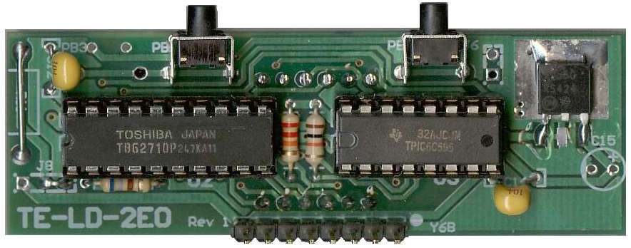
| 1 | ATMEGA8 | U1 | CPU |
| 1 | TB62710X | U2 | High side driver |
| 1 | TPIC6C595X | U3 | Low side sink |
| 1 | 74HC4052 | U4 | Mux |
| 1 | ST202 | U5 | RS232 |
| 1 | LM324 | U6 | Quad Op-amp |
| 1 | LMC6484 | U7 | Quad Op-amp |
| 1 | MC33204 | U8 | Quad Op-amp |
| 1 | DAC7612 | U9 | DAC (SMD already soldered) |
| 3 | LM7805C (D-PAK) | U10, U12 |
| 1 | MTP3055 (or NTP18N06G) | Q1 |
| 2 | 2N3904 | Q2, Q4 |
HEADERS / CONNECTORS
| 2 | wire link (no part) | J6, J8 |
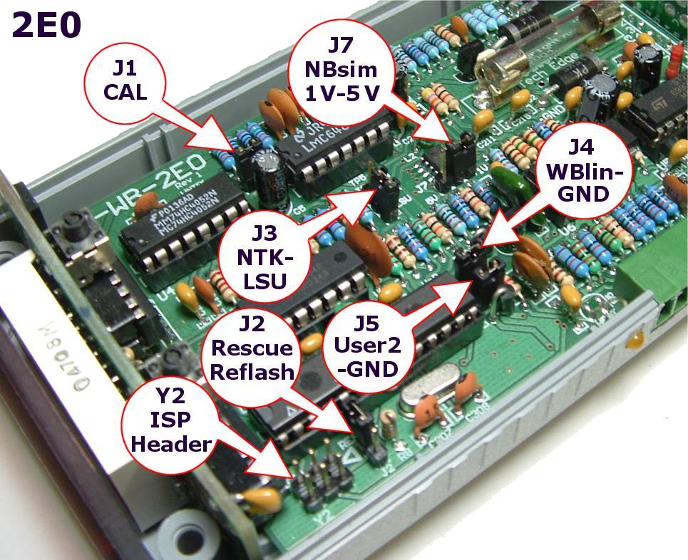
| 28 | HEADER pin STRIP | J1, J2, J3, J4, J5, J7, Y2, Y6A |
| 1 | 8 pin 90' SOCKET | Y6B | main PCB to display connector |
| 1 | RJ45 socket | Y1 | RS232 I/O and remote display |
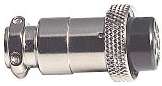
| 1 | 8 pin Circular Male | Y3 | Sensor cable connector |
| 1 | Molex MiniFit 2 pin | Y4 | PCB power connector |
| 1 | 3.81 mm 10 pin male | Y5A | I/O connector, PCB |
| 1 | 3.81 mm 10 pin female | Y5B | I/O connector, Screw |
| 1 | 28 pin 0.3" IC socket | U1S |
| 1 | 20 pin 0.3" IC socket | U2S |
| 3 | 16 pin IC socket | U3S, U4S, U5S |
| 3 | 14 pin IC socket | U6S, U7S, U8S |
| 1 | DB9 connector | for RS232 cable |
MISC
| 1 | 16MHz Crystal | X1 | |
| 2 | 33 or 100uH INDUCTOR | L1, L2 | CPU and DAC filter |
| 2 | N/O PUSHBUTTON | PB1, PB2 | control buttons |
| 1 | 10k TrimPot | R402 | | RPM filter |
| 1 | FUSE2 | FUSE | Fault protection |
| 2 | FUSEHOLDERS |
| 1 | Grey ABS Plastic Case | Drilled & machined, includes screws |
| 1 | Red acrylic lens | Machined to size |
| 1 | Printed sticker | over switches on case |
| 1 | case end | power, sensor & RJ45 case end |
| 4 | M3 bolts | PCB to case |
| 4 | M3 star washers | PCB to case |
| 6 | 0.1" jumper shunts | JS1, JS2, JS3, JS4, JS5, JS7 |
| 1 | DB9 backshell | with mounting hardware |
| 1 | RJ45 plug & cable | cable is pre-crimped to the plug |
| 1 | Cable tie | anchors DB9 wires to RS232 backshell |
| 1 | Power cable | pre-assembled 2m cable |
PARTS NOT INCLUDED
Depending on how you construct your WBo2 kit, some additional parts may be required.
- The 2E0 kit does not come with a Lambda sensor.
You can use a number of sensor including the Bosch 7057, 7200 & 6066 sensors
(Note 2E0 does not [yet] support the NTK L1H1 and L2H2 sensors).
Note that the firmware must be updated when switching from one sensor family to the other (ie. NTK UEGO <-> Bosch LSU).
Note also that the Bosch 31246 sensor is really an L1H1 sensor.
- Unless you buy the cable kit version of the 2E0 kit,
you will NOT have a mating female plug (Y3F shown here)
for the circular 8 pin male connector Y3. Y3F can be obtained from us by itself, or it's included with the cable kit.
- You also need a sensor connector kit that matches the type of sensor you have selected.
Parts Identification
 To view some of the components that people sometimes have difficulty identifying
Click on the image.
These include the inductors, the thermistor, and the 1% and 5% resistors.
Note also that none of the 100 ohm resistors used in WBo2 need not be any more accurate than 5%.
To view some of the components that people sometimes have difficulty identifying
Click on the image.
These include the inductors, the thermistor, and the 1% and 5% resistors.
Note also that none of the 100 ohm resistors used in WBo2 need not be any more accurate than 5%.
|
Resistors are shown in ohms and an R (=1), k (kilo=1000) or M (Mega=1,000,000)
indicates both the multiplier and the position of the decimal point.
Examples are :
| 100R | 100 ohms |
| 22k | 22 k ohms, or 22,000 ohms |
| 1M | 1 M ohms, or 1,000,000 ohms |
| 2M2 | 2.2 M ohms, or 2,200,00 ohms |
| 4R7 | 4.7 ohms |
| 0R22 | 0.22 ohms, or 220 milliohms |
Capacitors are measured in micro Farads (μ = Greek mu = 10-6 F),
nano Farads (n = nano = 10-9 F), and
pico Farads (p = pico = 10-12 F).
If the value is not clearly shown in μF then it will normally be measured
in picro Farads (pF) in the form of vvm where vv is the value and m
is the multiplier as a power of 10.
Examples are :
| 47 μF | 47 micro Farads (clearly printed) |
| 100 | 10 picro farads (pF), 10 -> value, multiplier -> 0 |
| 471 | 470 picro farads (pF), 47 -> value, multiplier -> 1 |
| 474 | 47 0000 pico Farads (pF), or 470 nano Farads (nF), or 0.47 μF |
Other common values are :
105 = 1.0 μF (1000 nF, or 1,000,000 pF),
104 = 0.1 μF (100 nF, or 100,000 pF),
103 = 0.01 μF (10 nF, or 10,000 pF),
102 = 0.001 μF (1 nF or 1,000 pF),
101 = 0.0001 μF (100 pF),
100 = 0.00001 μF = (10 pF)
Resistors in beige or brown (generally) have a tolerance of 5%,
and resistors in light blue or green have a tolerance of 1%
and the two types should not be mixed.
Capacitors are shown in μF (micro Farad), nF (nano Farad) and pF (Pico Farads).
|
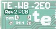
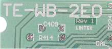 The DIY version of 2E0 was released at the start of 2005 and many people have build a working unit.
We made small changes to the Rev-1 layout to :
The DIY version of 2E0 was released at the start of 2005 and many people have build a working unit.
We made small changes to the Rev-1 layout to :
) To view some of the components that people sometimes have difficulty identifying
Click on the image.
These include the inductors, the thermistor, and the 1% and 5% resistors.
Note also that none of the 100 ohm resistors used in WBo2 need not be any more accurate than 5%.
To view some of the components that people sometimes have difficulty identifying
Click on the image.
These include the inductors, the thermistor, and the 1% and 5% resistors.
Note also that none of the 100 ohm resistors used in WBo2 need not be any more accurate than 5%.
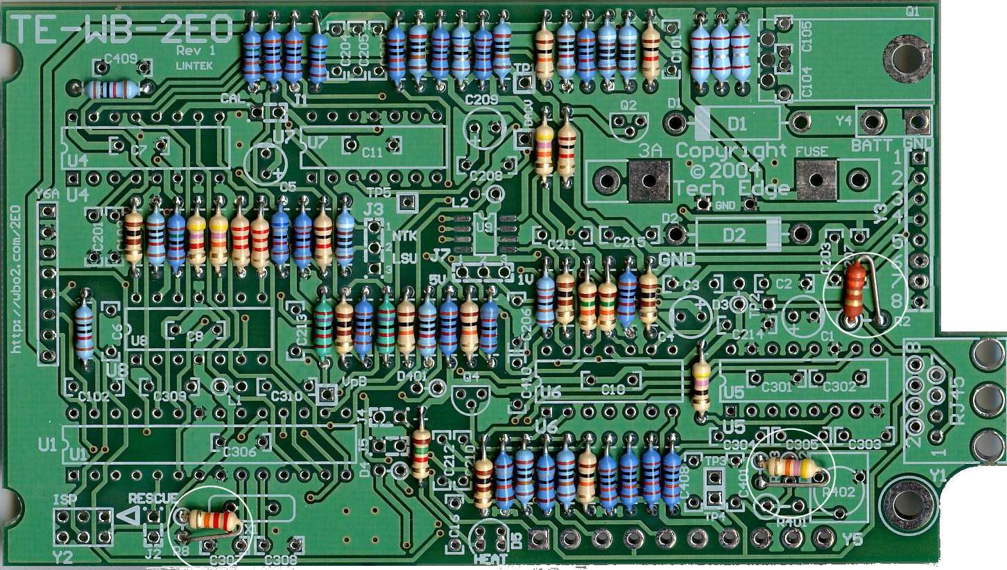
![Overlay & parts IDs, Rev-1 with Rev-2 annotations - [GIF]](im/2e0ovl.gif)
![Component values, Rev-1 with Rev-2 annotations [GIF]](im/2e0val.gif)
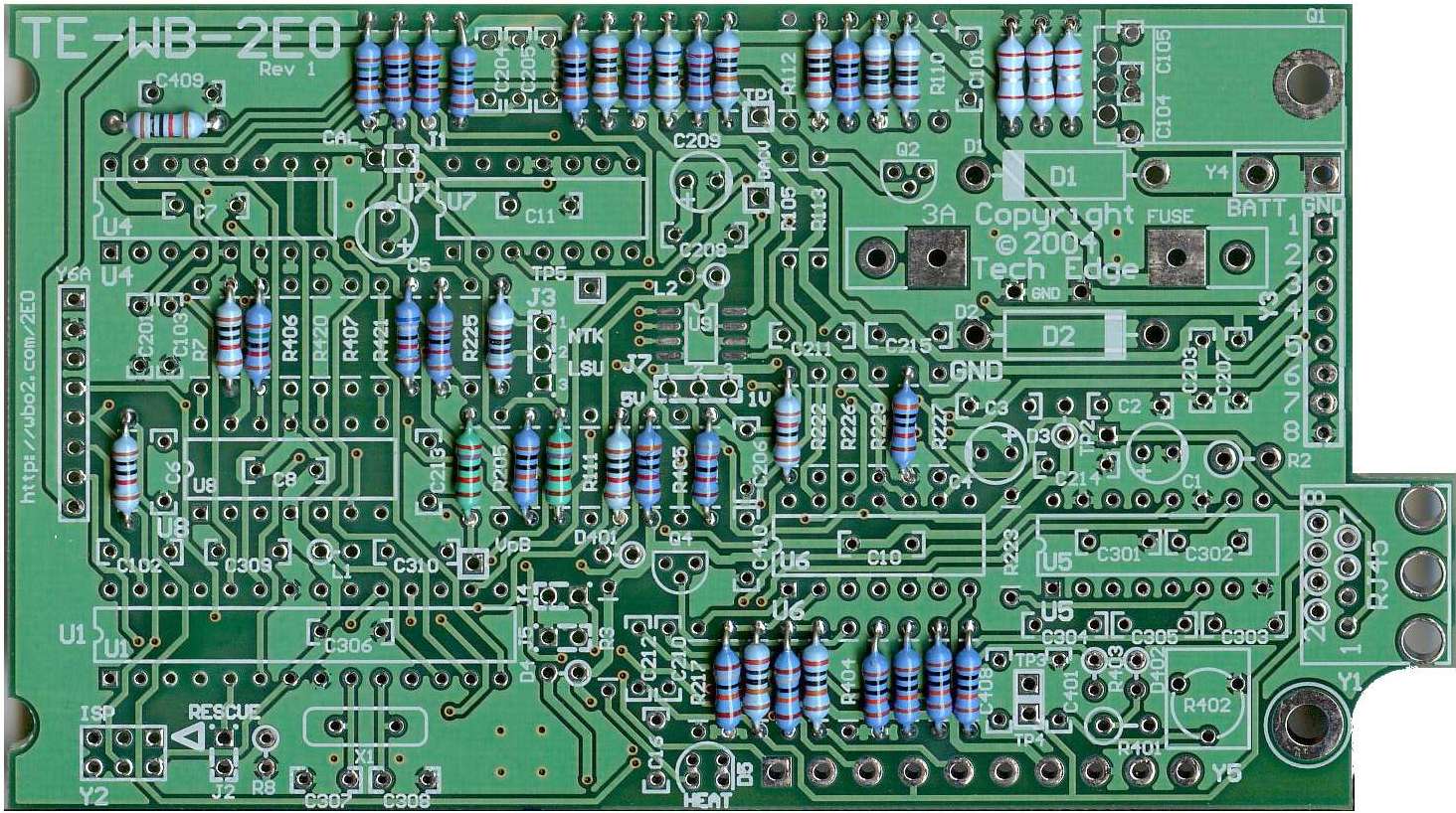
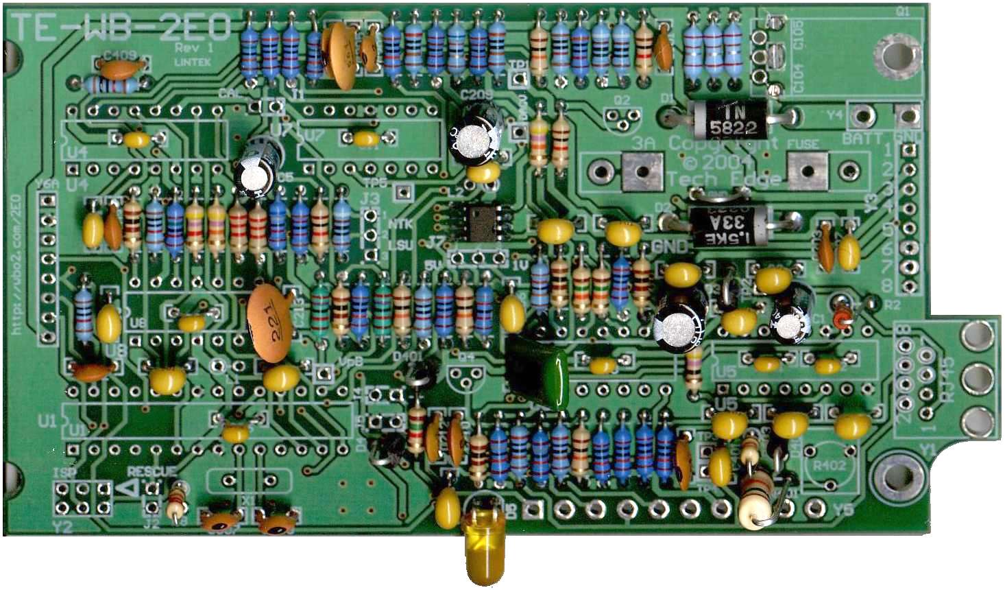
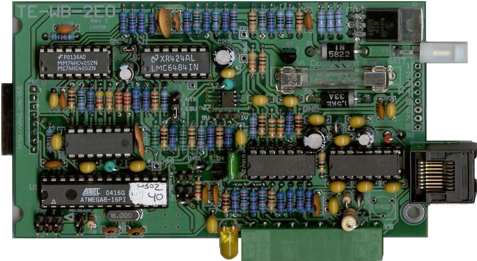
![Top of main board, Rev-1 [JPG]](im/pcbcompl.jpg)
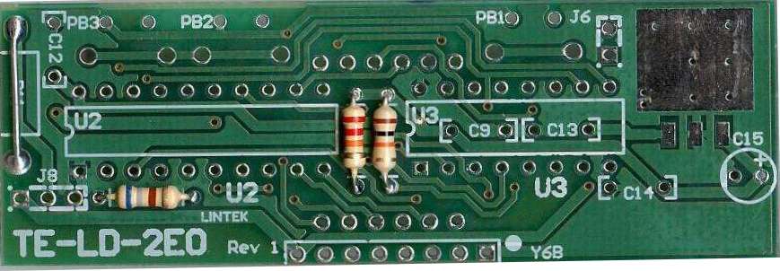
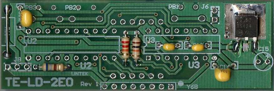
![Back of main board, Rev-1 [JPG]](im/pcbback.jpg)