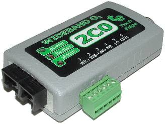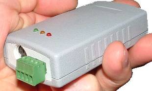
Production Unit. Rev-4 PCB and higher.
From April '05
|

Pre-production (Proto-2) Unit
December'04 - March'05
These notes are to help existing users find potential problems with units we have previously sold. All new units we sell contain any changes we have noted below. See here for the 2C0 Pre-Production Prototype.
Two basic 2C0 units have been released to date - they are easily distinguished :

Production Unit. Rev-4 PCB and higher.
|
|

Pre-production (Proto-2) Unit
|
Note : As of December 2005 a small number of Rev-5 PCB have been released to test our manufacturing capability of these boards. Full Rev-5 production will only take place after our stock of Rev-4 boards have been sold. This document will be updated when Rev-5 is generally available, but all Rev-4 2C0 units sold since July 2005 are guaranteed to have all the changes outlined below.
The 2C0's PCB rev-number can be found behind the circular 8 pin connector on Rev-4 and above. The Proto-2 PCB is the only PCB with the 6 pin DIN plug. Note: this page requires javascript to be turned ON.
![]() Index
| Unstable WBlin +/- Output
| Optimised WBlin +/- drive
Index
| Unstable WBlin +/- Output
| Optimised WBlin +/- drive
Unstable WBlin +/- Output - C212 [fixed from July 2005]

Problem : Under certain conditions the WBlin+/- outputs can be unstable and, in the worst case, may result in oscillations that make the WBlin output meaningless. The digital (RS232) wideband outputs are unaffected. NOT all units will be affected by this problem, as it depends on what the WBlin output is connected to. We suggest you check and modify your unit or get us to modify it for free (but freight costs may apply) if you have an unmodified PCB. Only pre Rev-5 PCBs (ie. Rev-4 boards manufactured before July 2005) are affected. The correct WBlin driver schematic is shown at right. The PCB layout error means that one side of C212 was connected to GND rather than across R219. Fixes for WBlin +/- Output [Pre July-2005, later units are OK] |
Rev-4 PCBThe fix is shown at left for Rev-4 PCBs sold before July 2005. Click on the image for a photo of where C212 and R219 are located (in front of the red & amber LEDs). Simply remove C212 (close to the red LED's leg) and place it over R219. removal is easily done with a fine soldering iron, solder wick, and possibly a stainless steel tool to move the heated C212. Soldering over R219 (body reads 2203) is even easier. Note that Rev-5 and above PCBs have C212 in the same place, but the traces have been moved. |
Pre-Production PCB (proto-2)
The fix for the pre-production (AKA Proto-2) PCB is a little more complicated to describe as C212 and R219 are on opposite sides of the PCB. The image shows C212 (top left corner) on the "component side". C212 must be removed carefully. Click on the left images for detail. Once removed, flip over the PCB and install C212 over R219 (face shows 2203) as at right. Click on the right image for details. |
Optimised WBlin +/- drive - R223 [fixed from July 2005]

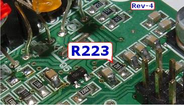
Some units were shipped with R223 of 1 k (marked as 102) rather than as 47 ohms. This is shown in the above schematic where the original 1k resistor (body reads 102) has been crossed out and replaced with 47R. This is a minor irritation and should cause no problems in the field, but It's worth making the change if you're opening the case anyway. The 1 k may have the effect of limiting the possible range of WBlin when the WBlin- reference goes much below 0 Volts, but this will only occur if you connect WBlin to a very low impedance input. |