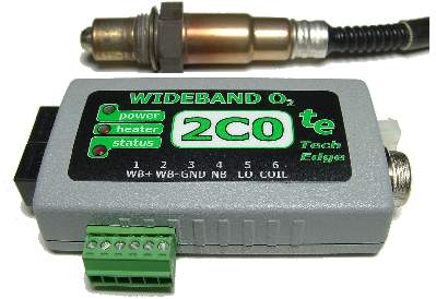
Tech Edge 2C0 Features
- Accuracy within 0.1 AFR (Lambda +/- 0.005).
- 12 bit differential WBlin output.
- 10.5 to 19.5 Volt DC operation (up to 3 Amps).
- Supports LSU 4.0/4.2 (Bosch 6066/7057 family) as well as NTK (L1H1/L2H2) sensor
(requires NTK sensor cable).
- NBsim narrowband output (10 bit PWM signal & configurable too).
- SVout 10 bit configurable (for LD01 display too).
- RPM input from Tacho or ECU for logging.
|
|
Buy the 2C0 - now sold out (Nov. 2009)
The original 2C0 has been supersceeded by the newer 2C0B unit
The 2C0B offers more features for a similar price, so go to that page for ordering information.
The rest of this document is the on-line user manual for the 2C0 (original - in grey case).
2C0 (original) Connection Overview
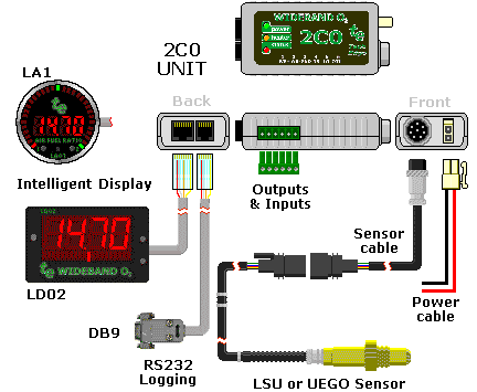
The image at left shows how 2C0 is connected to other WBo2 wideband components.
Some popup images of parts are available.
Clockwise from the bottom right, the LSU
(UEGO support may be offered later)
sensor is connected via the sensor cable
(comes in various lengths for different applications).
The sensor cable's
circular 8 pin connector mates with the 2C0 unit.
2C0 needs a source of power provided by the two pin power cable.
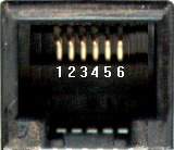
On the back of the case are an 8 pin (RJ45), and a 6 pin (RJ11) connector for PC RS232 connectivity (config & logging)
and for connection to an intelligent display.
The top of the case carries three status LEDs that show
power (GREEN), heater (AMBER) and operational (RED) status.
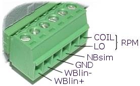
The side of the case carries a 6 pin green unpluggable connector with voltage outputs and RPM logging inputs.
The connectors and their inputs & outputs are described in detail below.
Also see the brief connector summary.
|
Note : To get 2C0 down to this size we had to leave off the analogue input channel logging features found in other models.
Many ECUs now have inbuilt logging so it's not too much of a restriction (and our other models cover this).
The unit does however have RPM logging.
2C0 (original) Technical Information
Technical Overview
| Outputs
| Inputs
| Jumper-shunts
| LED Diagnostics
| Logging
The 2C0 unit, without cables, weighs less than 70 grams, and measures 90 x 50 mm with height of 25 mm.
The connectors at the back plus front combined protrude a further 15 mm.
Sensor, power and display cables are compatible with the 2A0 unit
but the green pluggable logging & output connector is assigned differently to 2A0's.
The connectors are shown in the images below.
|
Front of 2C0, Y3 & Y2.
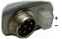
|
Side of 2C0, Y4.
|
Back of 2C0, Y1A & Y1B.
|
Click on each image to obtain a schematic view of the connectors
or see the brief connector summary.
2C0 Outputs = WBlin+/-, SVout, NBsim & RS232
As 2C0's major function is to measure AFR (or Lambda), the unit provides three (3)
software configurable 0 to 5 volt outputs
(WBlin, SVout & NBsim) that can be mapped to the the currently sensed AFR.
As well, an RS232 data stream provides digitally precise information on sensed AFR and all logged inputs.
These outputs are described in detail in the following paragraphs.
Note: Pin 3/Y1A refers to pin 3 on the 8 pin RJ45 connector Y1.
WBlin+ Pin 1/Y4 & WBlin- Pin 2/Y4 Wideband Output
The most accurate of the 3 voltage outputs is WBlin which is generated by a 12 bit DAC
using a 65 word lookup table (with linear interpolation).
A special feature of 2C0's WBlin is what we have called a differential output
which is designed to reduce the amount of noise and possible voltage offset errors seen by a device connected to WBlin.
The WBlin differential output is described fully here.
WBlin can be re-programmed using the Config utility
to cover any part of the AFR range from Lambda = 0.6 to free-air and 0 to 5 Volt output.
Note that pin 4/Y1A (8 pin RJ45) also carries the WBlin+ signal,
but remember that the WBlin-GND shunt (see details)
should be installed if this single ended output is used instead of the differential +/- output.
The default linear wideband output mapping is shown in the image at right.
To convert the default WBlin voltage to an AFR simply multiply the measured voltage by 2
and add 9. This is shown in the graph at left. The advantage of a linear output
is that it's easy to write a conversion function from the wideband voltage to AFR.
|
As well as WBlin the SVout & NBsim outputs are available.
They use a 10 bit PWM circuit which is less accurate (WBlin is 12 bits) and slightly noisier too.
Both outputs can be re-programmed using the Config utility.
SVout Pin 5/Y1B (5 on RJ45) Compatibility Output
To generate SVout, the processor uses a 65 word lookup table with linear interpolation.
It converts the normalised pump current (Ipx) into a 10 bit value representing SVout.
A hardware PWM (Pulse Width Modulation) pin on the processor generates the actual SVout voltage.
SVout is compatible with the Vout signal from the original
oz-diy-wb unit (and the 1.5 unit's Vwb).
It can be used to drive the analogue LD01 display (or the older 5301 if you change its connector).
Note that the 12 bit WBlin can be re-programmed to use the SVout table,
so if you're not using WBlin and you want a more accurate SVout voltage,
you should consider reprogramming WBlin.
Remember however that SVout covers the full range of full-rich (Lambda=0.6) to free-air, the voltage range is small (less than 3 Volts)
so measuring resolution is reduced compared to using a smaller AFR range over a larger voltage range.
The default SVout, shown at right, varies between about
1.0 Volt for a very rich mixture (Lambda=0.6 or AFR=9), to 2.50 Volts
for a stoic mixture, and to 3.1 Volts for a lean mixture (AFR=25).
In free-air the SVout should be exactly 4.00 Volts when the unit has been free-air calibrated correctly.
The default AFR vs. SVout relationship is shown in the Vout table/graph page.
The analogue Vout is a continuously available signal that may be logged with a high speed logger.
We recommend at least a 10 bit converter for best accuracy.
|
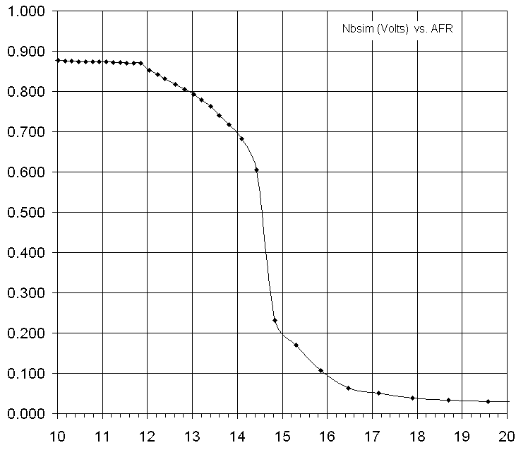
NBsim Pin 4/Y4 Simulated Narrowband Output
A synthesized narrowband (NBsim) voltage is produced by the onboard microcontroller
using a 10 bit A/D PWM converter (with single pole filter), and a 65 word lookup table. Linear interpolation improves lookup accuracy.
The full 0 to 5 Volt output is available, but restricting the output to 0 to 1 volt reduces the number of possible steps to around 200 (~5 mV per step).
As well as pin 4 of the green connector (Y4), pin 6/Y1A (8 pin RJ45) also carries the NBsim signal.
The NB output is designed to be compatible with
the raw output of a Bosch LSM-11 sensor. Refer to this
eXcel spreadsheet
for the graph of the default NBsim vs AFR.
As NBsim can re-programmed it is possible to do a number of
interesting things such as fooling the engine's ECU (if equipped with a NB sensor)
into running richer or leaner than it would do otherwise.
|
RS232 Rx Pin 2-RJ45 & Tx Pin 3-RJ45 Transmit/Receive

|
The 2C0's RJ45 connector (left black 8 pin connector) carries RS232 and other signals.
The unit transmits logged data on its Tx line [pin 3 - RJ45] and
receives commands (from PC or display) and code updates from a PC on its Rx line [pin 2 - RJ45].
The diagram at left shows the wires within the cable and also the connections at each end.
Note the pin names change from left to right - the WB unit's Tx pin transmits to the PC's Rx pin (and vice versa).
[pin 5 - RJ45] is the shield for the Rx and Tx data lines as well as being the return data path.
|
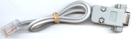
WBo2 to PC cable
Here's an image of the actual RS232 cable for connection between a PC and the WB unit.
The cable is used for either logging to a PC, or for re-flashing its code (under control of a PC).
If you need to extend the cable then a standard straight through male-female DB9 extension cable should be used
(ie. not a cross-over or null modem cable).
|
|
Other RJ45 Outputs - SVout,
NBsim,
WBlin+,
GND &
Vbatt
|

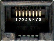 The SVout [pin 1],
WBlin+ [pin 4] &
NBsim [pin 6]
signals are all described in detail above.
The SVout signal is intended for analogue displays like the LD01 and
those displays will also use Vbatt & GND described below.
The RJ45 connector signal names are shown at right.
The SVout [pin 1],
WBlin+ [pin 4] &
NBsim [pin 6]
signals are all described in detail above.
The SVout signal is intended for analogue displays like the LD01 and
those displays will also use Vbatt & GND described below.
The RJ45 connector signal names are shown at right.
A fused, protected and partially filtered battery voltage Vbatt
is available from [pin 8] (right most RJ45 signal).
This output is provided to power other devices such as the LD02 display.
It should only be connected to devices that will draw small currents; typically less than 100 milliamps.
Excessive current consumption may cause heating of an internal dropping/protection resistor.
A ground GND point [pin 5-RJ45] is provided as a return for the RS232 and Vbatt connections.
Note that there are number of unconnected outputs (N/C = No Connection) on each of the RJ-45 connectors.
Those N/C's that have uses on other wideband units are shown "greyed in" and include WBlin (pin 4) and NBsim (pin 6).
|
6 Pin RJ11 Connector -
LSS Tx &
Rx, also
SVout,
WBlin+,
GND &
Vbatt
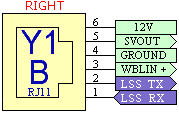 The right hand side RJ11 connector is designed for use with an intelligent serial display.
Its primary feature is a second serial channel called the Low Speed Serial (LSS) interface
which has a 1200 baud data rate (ie. low speed) which is adequate for most displays.
Additionally there are duplicates signals found on the RJ45 and green 6 pin connector.
The right hand side RJ11 connector is designed for use with an intelligent serial display.
Its primary feature is a second serial channel called the Low Speed Serial (LSS) interface
which has a 1200 baud data rate (ie. low speed) which is adequate for most displays.
Additionally there are duplicates signals found on the RJ45 and green 6 pin connector.
LSS Tx [pin 2] sends data frames to display.
LSS Rx [pin 1] is not currently supported in firmware.
Batt+ [pin 6] &
GND [pin 4]
provide current limited power and a return GND for the external display.
SVout [pin 5] &
WBlin+ [pin 3]
are described in sections above.
|
|
2C0 RPM Input
Tacho Input - RPMcoil (Pin 7/10) & RPMlo (Pin 8/10)
2C0 has a single RPM channel that is captured for logging.
Two inputs are provided, one for direct connection to a COIL (or a Tach signal
as generated by some vehicles) and another for a lower voltage "logic level" signal
as is generated by some sensors. Only one of the RPM inputs can be used at one time.
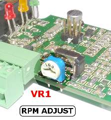
The image at right (click for popup enlargement)
shows the location of VR1 inside the 2C0 case.
VR1 can be adjusted to reject high frequency noise signals that sometimes interfere with RPM capture.
The RPM COIL input [pin 7/10] normally connects to the wire going between the points and the COIL.
On vehicles that have electronic ignition and a distributor,
you would connect to the point between the transistor switch (or ignition amplifier) and the coil.
The COIL input should never be connected to any voltage larger than 12 Volts or damage to the WBo2 unit may result.
The RPM Lo input [pin 8/10] can be connected to any lower voltage signal
that produces a 5 volt pulse at some small multiple of the engine's revs.
Unfortunately the loading (low input impedance) of the Lo input sometimes makes it infeasible to connect
to sensitive circuits such as an inductive crank angle sensor.
|
|
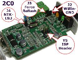
2C0 Jumper-Shunt Locations
The following sections describe how hardware options are set using on board jumper-shunts (often just called jumpers).
These shunts are :
- J2 - WBlin-GND jumper (on to select GND reference, more info. here).
- J3 - Rescue-Reflash jumper (in the NORMAL position except when rescue re-flashing).
- J4 - NTK-LSU selection jumper (as for the NTK or LSU sensor used) - Note: check for NTK firmware support.
- Y5 - ISP Header for programming (factory use - not described below).
Click on the image or here for an enlarged popup of the jumper-shunt locations.
|
WBlin - GND Reference [J2]
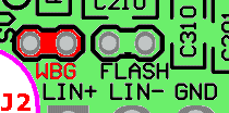 This shunt controls the WBlin+ output's reference input (WBlin-).
This topic is discussed here.
It is important to note that incorrectly setting this jumper can result in either:
This shunt controls the WBlin+ output's reference input (WBlin-).
This topic is discussed here.
It is important to note that incorrectly setting this jumper can result in either:
- Excessive WBlin+ noise (mostly heater switching transients at 30 Hz) on WBlin+
(with shunt installed = ON when it should be OFF and WBlin- goes to the input amp's GND).
- floating WBlin+ output that can exceed 5 Volts or go below 0 Volts
(shunt is OFF when WBlin- is left floating).
Note that if J2 is OFF, the effect of the J2 shunt can be reproduced by wiring pin 2/6 & 3/6
(ie. WBlin- to GND of the green connector) together with a short piece of wire.
This obviates opening the case to access J2 (but make sure J2 is off when you need it off!).
Click on the image for a photo-image popup.
To park the J2 shunt in the OFF position, place it on just one leg (as the other shunt is shown).
|
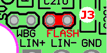
Reflashing - Firmware Updates [J3]
As mentioned in the software section, the
reflash utility is used to update the 2C0's firmware (or operating software).
The rescue jumper is not normally required to be used.
The image at right shows the location of the rescue-reflash jumper-shunt.
This normal position for the jumper-shunt when the unit is not being re-flashed is as shown in the
popup photo-image,
and the shunt is placed over both pins to enable the rescue mode.
|
NTK UEGO & Bosch LSU Support [J4]
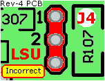
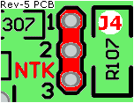 Note 1 :
The silkscreen around J4 shows either NTK (rev-4 PCB shown at left)
or LSU (Rev-5 PCB shown at right) -
Ignore these markings as the Rev-4 baord is incorrect -
simply note that :
Note 1 :
The silkscreen around J4 shows either NTK (rev-4 PCB shown at left)
or LSU (Rev-5 PCB shown at right) -
Ignore these markings as the Rev-4 baord is incorrect -
simply note that :

|
- 1-2 is the LSU position.
- 2-3 is the NTK position.
|
Note 2 : Support for the NTK (UEGO) sensor was added at firmware release 0549.
The 2C0 has hardware support for both the NTK UEGO sensor (L1H1, L2H2 & related models)
as well as the Bosch LSU sensor (all LSU 4.0 & 4.2 models).
Go here for more information on the sensors supported by 2C0,
but remember the sensor's actual connector may be different between otherwise compatible sensors.
To change the sensor between UEGO (NTK) and LSU (Bosch), two things must be done:
- Change the hardware which entails :
- Changing the 2C0-to-sensor cable to match the new sensor (see cable information here).
- Set J4 jumper shunt, for either the NTK or LSU.
Note carfully the warning about possible incorrect marking on the PCB - 1-2 is the J4 LSU position, 2-3 is the J4 NTK position.
- Change the firmware by re-flashing 2C0 with the latest firmware for that sensor.
Be very careful to match J4 jumper shunt's position to the NTK or LSU setting as
damage to the sensor or the 2C0 control unit may result.
This warning is particularly relevant if you swap from LSU to NTK - the NTK sensor may be destroyed!
Operation of the LEDs (Power, Heater, Status)

The unit has three LEDs. Their Normal operational status is described below. From left to right the LEDs are :
- GREEN = Power LED indicates power is connected. It should never be flashing.
- AMBER = Heater Power LED
shows the level of power being supplied to the sensor's heater.
It should flicker reasonably brightly at 30 Hz.
- RED = Status
LED flashes while the sensor is warming up, to indicate error conditions, and to indicating on-board logging status.
Diagnostics from the RED & AMBER LEDs
 Normal Operation :
The unit should always have a steady RED LED (unless on-board logging is active - see below).
The AMBER LED is brightly LIT but will flicker at 30 Hz (just perceptible).
The intensity of the AMBER flicker will give some idea of how much power is being used to maintain the heater's temperature.
Normal Operation :
The unit should always have a steady RED LED (unless on-board logging is active - see below).
The AMBER LED is brightly LIT but will flicker at 30 Hz (just perceptible).
The intensity of the AMBER flicker will give some idea of how much power is being used to maintain the heater's temperature.
 Normal - Heating :
Just after the unit has been turned on the normal heating cycle will cause the RED LED
to flash about once a second with a short sharp ON time, and longer OFF time.
The AMBER LED will produce a small amount of flicker (30 Hz), but should be brightly LIT.
This should last 20 to 30 seconds for a cold sensor.
If the time is much over 30 seconds then either the battery voltage may be low
or the sensor is placed where it is being excessively cooled by the gas flowing past it.
A cool sensor position may result in reduced sensor life and inaccurate measurements.
Normal - Heating :
Just after the unit has been turned on the normal heating cycle will cause the RED LED
to flash about once a second with a short sharp ON time, and longer OFF time.
The AMBER LED will produce a small amount of flicker (30 Hz), but should be brightly LIT.
This should last 20 to 30 seconds for a cold sensor.
If the time is much over 30 seconds then either the battery voltage may be low
or the sensor is placed where it is being excessively cooled by the gas flowing past it.
A cool sensor position may result in reduced sensor life and inaccurate measurements.
 Error - No Heating :
If the sensor cable is disconnected or damaged,
the battery voltage too low or too high,
or some other problem with the heater circuit occurs,
the RED LED will flash with a fast regular ON - OFF beat twice a second
While these conditions remain the AMBER LED will be mostly DIM
but will produce a very sharp flicker a few times a second
(the unit is looking for sensor or sampling battery voltage).
This condition can occur during starting or when there is excessive battery drain during idle.
It may be an indication of a poor battery or alternator/regulator, or connection to the wrong point of the vehicle's wiring.
Error - No Heating :
If the sensor cable is disconnected or damaged,
the battery voltage too low or too high,
or some other problem with the heater circuit occurs,
the RED LED will flash with a fast regular ON - OFF beat twice a second
While these conditions remain the AMBER LED will be mostly DIM
but will produce a very sharp flicker a few times a second
(the unit is looking for sensor or sampling battery voltage).
This condition can occur during starting or when there is excessive battery drain during idle.
It may be an indication of a poor battery or alternator/regulator, or connection to the wrong point of the vehicle's wiring.
Unlocked PID :
It's possible for transient conditions to cause the RED LED to flash off briefly.
As long as the AMBER LED and green POWER LED remain on
then this is an indication of a PID unlock condition.
A PID unlock is not necessarily an error, but it does indicate either very rapid changes in heating or cooling of the sensor,
and/or rapid changes in the ambient air-fuel ratio.
If this occurs without an explanation (such as rapid changes in throttle position) then it
may be an indication of an intermittent somewhere in the wiring, or an aging sensor.
Both the LD02 and the TEWBlog logger indicate these conditions.

The heater PID sharp single OFF flash is shown and prior to rev firmware Rev-48 this
single OFF flash was also used to indicate a wideband PID unlock too.
This condition indicates may indicate the sensor is positioned where it is either too hot or too cool.
 A wideband PID is now indicated by a sharp double OFF flash as shown here.
If you have earlier firmware and need to differentiate between the two conditions
then download the latest HXF flash files and update
(note, all 2A0 files start with version number 00).
A wideband PID is now indicated by a sharp double OFF flash as shown here.
If you have earlier firmware and need to differentiate between the two conditions
then download the latest HXF flash files and update
(note, all 2A0 files start with version number 00).
|
Serial Logging & Software
2C0 does not store data on-board like other WBo2 models.
But a serial data stream is available to be logged to a PC or other RS232 device.
Win32 and other platform Logging software is available right now.
|
Further Information
We update 2C0 documentation from time-to-time in response to your Feedback.
The latest version of this product is described here.
Tech Edge had a prototype of the 2C0 that we sold in very limited quantities.
Here is the specific information on the 2C0 pre-production prototype.
|
)
)
)
)
)
)
)
)
)
)
)
)
)
)
)
)
)