This page describes how to get on-board logging working for WBo2 2A0. Briefly, you need to add a 32 k byte serial EEPROM chip and a switch to control it. There is now a low cost DIY upgrade (log-mod kit) available to do this. See the Logger Tech Info. pages for logger specification and how to use it. Note : The extra parts described here for logging are now included in all 2A0 DIY kits

Note : This page relates to the 32k byte logger upgrade that has been present on all 2A0 pre-built units and DIY kits since late 2003. We have retained the page for compatibility issues and historic reasons. You may be more interested in the 1 MByte upgrade ...

Introduction - On-Board Logging

WBo2 has provision for on-board logging using an 8 pin 32 k byte serial EEPROM chip. On-board logging stores up to 32 k bytes of data on the WBo2 unit itself without WBo2 having to be connected to a PC or a PDA. Logging is controlled by a single switch that can be wired into WBo2 locally or remotely. User feedback for on-board logging is provided by WBo2's red LED (which also provides general-status feedback). More information on how logging works can be found in the WBo2 Logging Info. and Specs. page.

See the end of this article for details of how to purchase the Log-Mod kit for US$6.00 (approx = AU$7.50).

Log-Mod DIY kit contents

The logger modification kit shown here contains the following parts (listed clockwise from left) :


    22 k ohm 5% resistor
    press button switch
    100 n F (104) capacitor
    32 k bytes EEPROM chip (ST-M24256)
    PCB header/standoff (10 x 1 strip)
    header pins (6 x 1 strip)

Additional Logger Hardware

The schematic for the on-board logging modifications are shown at right. This circuit is common for the rev-2 & rev-3 PCBs but only the rev-3 PCB has provision for the switch.

A 22 k ohm pull-up resistor R303, wired to +5V (also pin 1 Y5), defines the press button PB1's off logic level. A 100 nF capacitor C311 provides some noise filtering if the switch PB1 is externally mounted. Optionally a 6 volt zener diode (not supplied in any kits) can also be wired across an external PB1 for further protection.

Adding On-board Logging Hardware

Rev-3 PCB

The Rev-3 PCB is readily identified as it has provision for the press button switch PB1 (in the lower left of the PCB) just to the left of the 28 pin processor U1. Check the rev-3 component overlay or the WBo2 location guide.

The image at left show the final mounted press button switch assembly.

Note also in this image the link for the RPM jumper from the 5K to the 504 hole.

The resistor and capacitor can be added first. 22 k resistor R303 is located immediately to the right of the 28 pin processor. 100 n F (104) capacitor C311 is just above the press button PB1.

The press button (PB1) cannot be simply soldered onto the PCB as its shaft is too short. PB1 must be mounted on pins that push into a header that is soldered to the PCB.

First cut the single strip of 6 pins into two strips of 3 pins - the two outer pins become "legs" for PB1. solder the legs as shown in the image at left (both the side and the end views are shown).

The supplied header strip must be cut into two strips each with 3 holes. the centre "header" cannot be used (as there is no hole in the PCB for it) and the central metal part should be pulled out leaving the two end "headers" that can now be soldered into the PB1 position. This is shown in the image at far right. The image at left shows the PB1 assembly with the header strip before the header is soldered to the PCB.

The button with attached pins, from the previous step, is then pushed into the header on the PCB thus extending the button the correct distance from the PCB so it now just protrudes through the grey case. Of course, you may need to drill a hole for the button (3.2 mm or 1/8") should be sufficient.

Adding On-board Logging Hardware - Rev-2 PCB

The first released 2A0 wideband PCB used the rev-2 step and it shipped from August 2003 until early November 2003, and was replaced with the rev-3 step that incorporates minor artwork changes and adds the PB1 button described above.

The Rev-2 PCB has an artwork error that prevents the EEPROM chip from being simply dropped in, small changes must be made to the PCB. (Note : The Rev-3 PCB has corrected the artwork). The image at right shows the Rev-2 PCB changes made around the bottom left hand corner (Note : this becomes the top left when flipped and looking at the solder side). Two traces are cut where the arrows point, and the two red wires have been added to rejoin the cut traces to the correct signals (the data and clock lines were reversed).

Refer to the schematic above (rev-3 and rev-2 use the same circuit).

The 22 k ohm pull-up resistor R303, wired to +5V (pin 1 Y5), defines the off logic level, and a 100 nF capacitor C311 provides some noise filtering for externally mounted switches. The image at left shows these two components mounted underneath the PCB (ie. on the solder side). Optionally a 6 volt zener diode (not shown) can also be wired across the switch for further protection.

When wiring the components, take particular note of the fact that Y5 pin 8 is not actually connected to GND on the PCB. A small area of the green solder resist should be scraped off and tinned so the capacitor's leg will solder pin 8 to the adjacent GND area. This is shown in the image at right.

Mounting a Remote Logging Switch (Rev-2/3)

Although the rev-3 PCB has provision for a press button, a remote button can be added for convenience. The following paragraphs are most applicable to the rev-2 PCB.

To control logging, the press button switch PB1 can be mounted on the case somewhere (with short flexible leads), or remotely using a longer cable. 
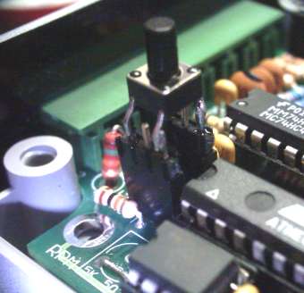
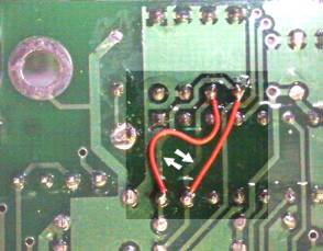
We illustrate below a possible way of attaching a longer cable to the unit.

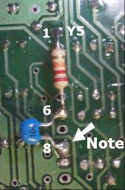
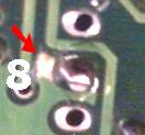
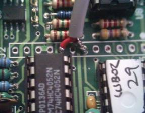
The image at right shows a single core shielded cable wired to Y5 pins 6 and 8. Note that the shield goes to pin 8 (GND) and is attached to the component side of the PCB.

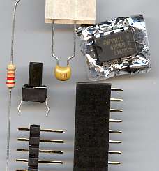
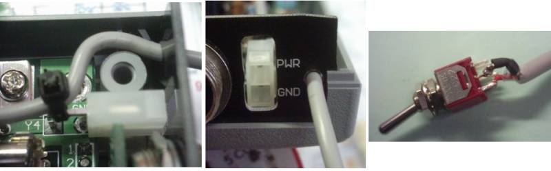
The image montage below shows a way of mounting the remote switch. 
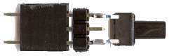
The switch in this case is a spring loaded toggle switch. A conventional press button could have been used.
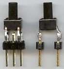
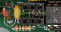
<